ISO/IEC JTC1/SC29/WG11N6828
Palma de Mallorca, October 2004
| Title | MPEG-7 Overview (version 10) |
| Status | Approved |
| Source | Requirements |
| Editor | José M. Martínez (UAM-EPS-GTI, ES) |
MPEG-7 is an ISO/IEC standard developed by MPEG (Moving Picture Experts Group), the committee that also developed the Emmy Award winning standards known as MPEG-1 and MPEG-2, and the MPEG-4 standard. MPEG-1 and MPEG-2 standards made interactive video on CD-ROM and Digital Television possible. MPEG-4 is the multimedia standard for the fixed and mobile web enabling integration of multiple paradigms.
MPEG-7, formally named "Multimedia Content Description Interface", is a standard for describing the multimedia content data that supports some degree of interpretation of the information meaning, which can be passed onto, or accessed by, a device or a computer code. MPEG-7 is not aimed at any one application in particular; rather, the elements that MPEG-7 standardizes support as broad a range of applications as possible.
More information about MPEG-7 can be found at the MPEG home page (http://www.chiariglione.org/mpeg) and the MPEG Industry Forum website (http://www.mpegif.org), which contain links to a wealth of information about MPEG, including much about MPEG-7, many publicly available documents, several lists of ‘Frequently Asked Questions’ and links to other MPEG-7 web pages.
This document gives an overview of the MPEG-7 standard, explaining which pieces of technology it includes and what sort of applications are supported by this technology. Also the current work towards MPEG-7 version 2 is presented.
Accessing audio and video used to be a simple matter - simple because of the simplicity of the access mechanisms and because of the poverty of the sources. An incommensurable amount of audiovisual information is becoming available in digital form, in digital archives, on the World Wide Web, in broadcast data streams and in personal and professional databases, and this amount is only growing. The value of information often depends on how easy it can be found, retrieved, accessed, filtered and managed.
The transition between the second and third millennium abounds with new ways to produce, offer, filter, search, and manage digitized multimedia information. Broadband is being offered with increasing audio and video quality and speed of access. The trend is clear: in the next few years, users will be confronted with such a large number of contents provided by multiple sources that efficient and accurate access to this almost infinite amount of content seems unimaginable today. In spite of the fact that users have increasing access to these resources, identifying and managing them efficiently is becoming more difficult, because of the sheer volume. This applies to professional as well as end users. The question of identifying and managing content is not just restricted to database retrieval applications such as digital libraries, but extends to areas like broadcast channel selection, multimedia editing, and multimedia directory services.
This challenging situation demands a timely solution to the problem. MPEG-7 is the answer to this need.
MPEG-7 is an ISO/IEC standard developed by MPEG (Moving Picture Experts Group), the committee that also developed the successful standards known as MPEG-1 (1992) and MPEG-2 (1994), and the MPEG-4 standard (Version 1 in 1998, and version 2 in 1999). The MPEG-1 and MPEG-2 standards have enabled the production of widely adopted commercial products, such as Video CD, MP3, digital audio broadcasting (DAB), DVD, digital television (DVB and ATSC), and many video-on-demand trials and commercial services. MPEG-4 is the first real multimedia representation standard, allowing interactivity and a combination of natural and synthetic material coded in the form of objects (it models audiovisual data as a composition of these objects). MPEG-4 provides the standardized technological elements enabling the integration of the production, distribution and content access paradigms of the fields of interactive multimedia, mobile multimedia, interactive graphics and enhanced digital television.
The MPEG-7 standard, formally named "Multimedia Content Description Interface", provides a rich set of standardized tools to describe multimedia content. Both human users and automatic systems that process audiovisual information are within the scope of MPEG-7.
MPEG-7 offers a comprehensive set of audiovisual Description Tools (the metadata elements and their structure and relationships, that are defined by the standard in the form of Descriptors and Description Schemes) to create descriptions (i.e., a set of instantiated Description Schemes and their corresponding Descriptors at the users will), which will form the basis for applications enabling the needed effective and efficient access (search, filtering and browsing) to multimedia content. This is a challenging task given the broad spectrum of requirements and targeted multimedia applications, and the broad number of audiovisual features of importance in such context.
MPEG-7 has been developed by experts representing broadcasters, electronics manufacturers, content creators and managers, publishers, intellectual property rights managers, telecommunication service providers and academia.
More information about MPEG-7 can be found at the MPEG website (http://www.chiariglione.org/mpeg ), the MPEG-7 Industry Forum website (http://www.mpegif.com), and the MPEG-7 Consortium website (http://mpeg7.nist.gov). These web pages contain links to a wealth of information about MPEG, including much about MPEG-7, many publicly available documents, several lists of ‘Frequently Asked Questions’ and links to other MPEG-7 web pages.
Audiovisual information plays an important role in our society, be it recorded in such media as film or magnetic tape or originating, in real time, from some audio or visual sensors and be it analogue or, increasingly, digital. Everyday, more and more audiovisual information is available from many sources around the world and represented in various forms (modalities) of media, such as still pictures, graphics, 3D models, audio, speech, video, and various formats. While audio and visual information used to be consumed directly by the human being, there is an increasing number of cases where the audiovisual information is created, exchanged, retrieved, and re-used by computational systems. This may be the case for such scenarios as image understanding (surveillance, intelligent vision, smart cameras, etc.) and media conversion (speech to text, picture to speech, speech to picture, etc.). Other scenarios are information retrieval (quickly and efficiently searching for various types of multimedia documents of interest to the user) and filtering in a stream of audiovisual content description (to receive only those multimedia data items which satisfy the user preferences). For example, a code in a television program triggers a suitably programmed PVR (Personal Video Recorder) to record that program, or an image sensor triggers an alarm when a certain visual event happens. Automatic transcoding may be performed from a string of characters to audible information or a search may be performed in a stream of audio or video data. In all these examples, the audiovisual information has been suitably "encoded" to enable a device or a computer code to take some action.
Audiovisual sources will play an increasingly pervasive role in our lives, and there will be a growing need to have these sources processed further. This makes it necessary to develop forms of audiovisual information representation that go beyond the simple waveform or sample-based, compression-based (such as MPEG-1 and MPEG-2) or even objects-based (such as MPEG-4) representations. Forms of representation that allow some degree of interpretation of the information meaning are necessary. These forms can be passed onto, or accessed by, a device or a computer code. In the examples given above an image sensor may produce visual data not in the form of PCM samples (pixels values) but in the form of objects with associated physical measures and time information. These could then be stored and processed to verify if certain programmed conditions are met. A PVR could receive descriptions of the audiovisual information associated to a program that would enable it to record, for example, only news with the exclusion of sport. Products from a company could be described in such a way that a machine could respond to unstructured queries from customers making inquiries.
MPEG-7 is a standard for describing the multimedia content data that will support these operational requirements. The requirements apply, in principle, to both real-time and non real-time as well as push and pull applications. MPEG-7 does not standardize or evaluate applications, although in the development of the MPEG-7 standard applications have been used for understanding the requirements and evaluation of technology. It must be made clear that the requirements are derived from analyzing a wide range of potential applications that could use MPEG-7 tools. MPEG-7 is not aimed at any one application in particular; rather, the elements that MPEG-7 standardizes support as broad a range of applications as possible.
In October 1996, MPEG started a new work item to provide a solution to the questions described above. The new member of the MPEG family, named "Multimedia Content Description Interface" (in short MPEG-7), provides standardized core technologies allowing the description of audiovisual data content in multimedia environments. It extends the limited capabilities of proprietary solutions in identifying content that exist today, notably by including more data types.
Audiovisual data content that has MPEG-7 descriptions associated with it, may include: still pictures, graphics, 3D models, audio, speech, video, and composition information about how these elements are combined in a multimedia presentation (scenarios). A special case of these general data types is facial characteristics.
MPEG-7 descriptions do, however, not depend on the ways the described content is coded or stored. It is possible to create an MPEG-7 description of an analogue movie or of a picture that is printed on paper, in the same way as of digitized content.
MPEG-7 allows different granularity in its descriptions, offering the possibility to have different levels of discrimination. Even though the MPEG-7 description does not depend on the (coded) representation of the material, MPEG-7 can exploit the advantages provided by MPEG-4 coded content. If the material is encoded using MPEG-4, which provides the means to encode audio-visual material as objects having certain relations in time (synchronization) and space (on the screen for video, or in the room for audio), it will be possible to attach descriptions to elements (objects) within the scene, such as audio and visual objects.
Because the descriptive features must be meaningful in the context of the application, they will be different for different user domains and different applications. This implies that the same material can be described using different types of features, tuned to the area of application. To take the example of visual material: a lower abstraction level would be a description of e.g. shape, size, texture, color, movement (trajectory) and position (‘where in the scene can the object be found?); and for audio: key, mood, tempo, tempo changes, position in sound space. The highest level would give semantic information: ‘This is a scene with a barking brown dog on the left and a blue ball that falls down on the right, with the sound of passing cars in the background.’ Intermediate levels of abstraction may also exist.
The level of abstraction is related to the way the features can be extracted: many low-level features can be extracted in fully automatic ways, whereas high level features need (much) more human interaction.
Next to having a description of what is depicted in the content, it is also required to include other types of information about the multimedia data:
· The form - An example of the form is the coding format used (e.g. JPEG, MPEG-2), or the overall data size. This information helps determining whether the material can be ‘read’ by the user terminal;
· Conditions for accessing the material - This includes links to a registry with intellectual property rights information, and price;
· Classification - This includes parental rating, and content classification into a number of pre-defined categories;
· Links to other relevant material - The information may help the user speeding up the search;
· The context - In the case of recorded non-fiction content, it is very important to know the occasion of the recording (e.g. Olympic Games 1996, final of 200 meter hurdles, men).
The main elements of the MPEG-7 standard are:
· Description Tools: Descriptors (D), that define the syntax and the semantics of each feature (metadata element); and Description Schemes (DS), that specify the structure and semantics of the relationships between their components, that may be both Descriptors and Description Schemes;
· A Description Definition Language (DDL) to define the syntax of the MPEG-7 Description Tools and to allow the creation of new Description Schemes and, possibly, Descriptors and to allow the extension and modification of existing Description Schemes;
· System tools, to support binary coded representation for efficient storage and transmission, transmission mechanisms (both for textual and binary formats), multiplexing of descriptions, synchronization of descriptions with content, management and protection of intellectual property in MPEG-7 descriptions, etc.
Therefore, MPEG-7 Description Tools allows to create descriptions (i.e., a set of instantiated Description Schemes and their corresponding Descriptors at the users will), to incorporate application specific extensions using the DDL and to deploy the descriptions using System tools.
The MPEG-7 descriptions of content that may include:
· Information describing the creation and production processes of the content (director, title, short feature movie).
· Information related to the usage of the content (copyright pointers, usage history, broadcast schedule).
· Information of the storage features of the content (storage format, encoding).
· Structural information on spatial, temporal or spatio-temporal components of the content (scene cuts, segmentation in regions, region motion tracking).
· Information about low level features in the content (colors, textures, sound timbres, melody description).
· Conceptual information of the reality captured by the content (objects and events, interactions among objects).
· Information about how to browse the content in an efficient way (summaries, variations, spatial and frequency subbands,).
· Information about collections of objects.
· Information about the interaction of the user with the content (user preferences, usage history).
All these descriptions are of course coded in an efficient way for searching, filtering, etc.
To accommodate this variety of complementary content descriptions, MPEG-7 approaches the description of content from several viewpoints. The sets of Description Tools developed on those viewpoints are presented here as separate entities. However, they are interrelated and can be combined in many ways. Depending on the application, some will present and others can be absent or only partly present.
A description generated using MPEG-7 Description Tools will be associated with the content itself, to allow fast and efficient searching for, and filtering of material that is of interest to the user.
MPEG-7 data may be physically located with the associated AV material, in the same data stream or on the same storage system, but the descriptions could also live somewhere else on the globe. When the content and its descriptions are not co-located, mechanisms that link the multimedia material and their MPEG-7 descriptions are needed; these links will have to work in both directions.
MPEG-7 addresses many different applications in many different environments, which means that it needs to provide a flexible and extensible framework for describing audiovisual data. Therefore, MPEG-7 does not define a monolithic system for content description but rather a set of methods and tools for the different viewpoints of the description of audiovisual content. Having this in mind, MPEG-7 is designed to take into account all the viewpoints under consideration by other leading standards such as, among others, TV Anytime, Dublin Core, SMPTE Metadata Dictionary, and EBU P/Meta. These standardization activities are focused to more specific applications or application domains, whilst MPEG-7 has been developed as generic as possible. MPEG-7 uses also XML as the language of choice for the textual representation of content description, as XML Schema has been the base for the DDL (Description Definition Language) that is used for the syntactic definition of MPEG-7 Description Tools and for allowing extensibility of Description Tools (either new MPEG-7 ones or application specific). Considering the popularity of XML, usage of it will facilitate interoperability with other metadata standards in the future.
MPEG-7 addresses applications that can be stored (on-line or off-line) or streamed (e.g. broadcast, push models on the Internet), and can operate in both real-time and non real-time environments. A ‘real-time environment’ in this context means that the description is generated while the content is being captured.
Figure 1 below shows a highly abstract block diagram of a possible MPEG-7 processing chain, included here to explain the scope of the MPEG-7 standard. This chain includes feature extraction (analysis), the description itself, and the search engine (application). To fully exploit the possibilities of MPEG-7 descriptions, automatic extraction of features will be extremely useful. It is also clear that automatic extraction is not always possible, however. As was noted above, the higher the level of abstraction, the more difficult automatic extraction is, and interactive extraction tools will be of good use. However useful they are, neither automatic nor semi-automatic feature extraction algorithms are inside the scope of the standard. The main reason is that their standardization is not required to allow interoperability, while leaving space for industry competition. Another reason not to standardize analysis is to allow making good use of the expected improvements in these technical areas.
Also the search engines, filter agents, or any other program that can make use of the description, are not specified within the scope of MPEG-7; again this is not necessary, and here too, competition will produce the best results.

Figure 2 shows the relationship among the different MPEG-7 elements introduced above. The DDL allows the definition of the MPEG-7 description tools, both Descriptors and Description Schemes, providing the means for structuring the Ds into DSs. The DDL also allows the extension for specific applications of particular DSs. The description tools are instantiated as descriptions in textual format (XML) thanks to the DDL (based on XML Schema). Binary format of descriptions is obtained by means of the BiM defined in the Systems part.
Figure 3 explains a hypothetical MPEG-7 chain in practice [ There can be other streams from content to user; these are not depicted here. Furthermore, it is understood that the MPEG-7 Coded Description may be textual or binary, as there might be cases where a binary efficient representation of the description is not needed, and a textual representation would suffice.] . From the multimedia content an Audiovisual description is obtained via manual or semi-automatic extraction. The AV description may be stored (as depicted in the figure) or streamed directly. If we consider a pull scenario, client applications will submit queries to the descriptions repository and will receive a set of descriptions matching the query for browsing (just for inspecting the description, for manipulating it, for retrieving the described content, etc.). In a push scenario a filter (e.g., an intelligent agent) will select descriptions from the available ones and perform the programmed actions afterwards (e.g., switching a broadcast channel or recording the described stream). In both scenarios, all the modules may handle descriptions coded in MPEG-7 formats (either textual or binary), but only at the indicated conformance points it is required to be MPEG-7 conformant (as they show the interfaces between an application acting as information server and information consumer).The emphasis of MPEG-7 is the provision of novel solutions for audio-visual content description. Thus, addressing text-only documents was not among the goals of MPEG-7. However, audio-visual content may include or refer to text in addition to its audio-visual information. MPEG-7 therefore has standardized different Description Tools for textual annotation and controlled vocabularies, taking into account existing standards and practices.1.4 MPEG-7 Application Areas
The elements that MPEG-7 standardizes provide support to a broad range of applications (for example, multimedia digital libraries, broadcast media selection, multimedia editing, home entertainment devices, etc.). MPEG-7 will also make the web as searchable for multimedia content as it is searchable for text today. This would apply especially to large content archives, which are being made accessible to the public, as well as to multimedia catalogues enabling people to identify content for purchase. The information used for content retrieval may also be used by agents, for the selection and filtering of broadcasted "push" material or for personalized advertising. Additionally, MPEG-7 descriptions will allow fast and cost-effective usage of the underlying data, by enabling semi-automatic multimedia presentation and editing.
All application domains making use of multimedia will benefit from MPEG-7. Considering that at present day it is hard to find one not using multimedia, please extend the list of the examples below using your imagination:
· Architecture, real estate, and interior design (e.g., searching for ideas).
· Broadcast media selection (e.g., radio channel, TV channel).
· Cultural services (history museums, art galleries, etc.).
· Digital libraries (e.g., image catalogue, musical dictionary, bio-medical imaging catalogues, film, video and radio archives).
· E-Commerce (e.g., personalized advertising, on-line catalogues, directories of e-shops).
· Education (e.g., repositories of multimedia courses, multimedia search for support material).
· Home Entertainment (e.g., systems for the management of personal multimedia collections, including manipulation of content, e.g. home video editing, searching a game, karaoke).
· Investigation services (e.g., human characteristics recognition, forensics).
· Journalism (e.g. searching speeches of a certain politician using his name, his voice or his face).
· Multimedia directory services (e.g. yellow pages, Tourist information, Geographical information systems).
· Multimedia editing (e.g., personalized electronic news service, media authoring).
· Remote sensing (e.g., cartography, ecology, natural resources management).
· Shopping (e.g., searching for clothes that you like).
· Social (e.g. dating services).
· Surveillance (e.g., traffic control, surface transportation, non-destructive testing in hostile environments).
The way MPEG-7 descriptions will be used to answer user queries or filtering operations is outside the scope of the standard. The type of content and the query do not have to be the same; for example, visual material may be queried and filtered using visual content, music, speech, etc. It is the responsibility of the search engine and filter agent to match the query data to the MPEG-7 description.
· Play a few notes on a keyboard and retrieve a list of musical pieces similar to the required tune, or images matching the notes in a certain way, e.g. in terms of emotions.
· Draw a few lines on a screen and find a set of images containing similar graphics, logos, ideograms,...
· Define objects, including color patches or textures and retrieve examples among which you select the interesting objects to compose your design.
· On a given set of multimedia objects, describe movements and relations between objects and so search for animations fulfilling the described temporal and spatial relations.
· Describe actions and get a list of scenarios containing such actions.
· Using an excerpt of Pavarotti’s voice, obtaining a list of Pavarotti’s records, video clips where Pavarotti is singing and photographic material portraying Pavarotti.
The MPEG-7 Standard consists of the following parts:
1. MPEG-7 Systems – the tools needed to prepare MPEG-7 descriptions for efficient transport and storage and the terminal architecture.
2. MPEG-7 Description Definition Language - the language for defining the syntax of the MPEG-7 Description Tools and for defining new Description Schemes.
3. MPEG-7 Visual – the Description Tools dealing with (only) Visual descriptions.
4. MPEG-7 Audio – the Description Tools dealing with (only) Audio descriptions.
5. MPEG-7 Multimedia Description Schemes - the Description Tools dealing with generic features and multimedia descriptions.
6. MPEG-7 Reference Software - a software implementation of relevant parts of the MPEG-7 Standard with normative status.
7. MPEG-7 Conformance Testing - guidelines and procedures for testing conformance of MPEG-7 implementations
8. MPEG-7 Extraction and use of descriptions – informative material (in the form of a Technical Report) about the extraction and use of some of the Description Tools.
9. MPEG-7 Profiles and levels - provides guidelines and standard profiles.
10. MPEG-7 Schema Definition - specifies the schema using the Description Definition Language
Besides the different official MPEG-7 parts, there are also MPEG-7 Liaisons within the broader scope of the MPEG Liaisons activity. MPEG Liaisons deals with organizing formal collaboration between MPEG and other related activities under development in other standardization bodies. Currently MPEG-7 related liaisons include, among others, SMPTE, TV-Anytime, EBU P/Meta, Dublin Core and W3C.
1.6 Method of Work and Development Schedule
The method of development has been comparable to that of the previous MPEG standards. MPEG work is usually carried out in three stages: definition, competition, and collaboration. In the definition phase, the scope, objectives and requirements for MPEG-7 were defined. In the competitive stage, participants worked on their technology by themselves. The end of this stage was marked by the MPEG-7 Evaluation following an open Call for Proposals (CfP). The Call asked for relevant technology fitting the requirements. In answer to the Call, all interested parties, no matter whether they participate or have participated in MPEG, were invited to submit their technology to MPEG. Some 60 parties submitted, in total, almost 400 proposals, after which MPEG made a fair expert comparison between these submissions.
Selected elements of different proposals were incorporated into a common model (the eXperimentation Model, or XM) during the collaborative phase of the standard with the goal of building the best possible model, which was in essence a draft of the standard itself. During the collaborative phase, the XM was updated and improved in an iterative fashion, until MPEG-7 reached the Committee Draft (CD) stage in October 2000, after several versions of the Working Draft. Improvements to the XM were made through Core Experiments (CEs). CEs were defined to test the existing tools against new contributions and proposals, within the framework of the XM, according to well-defined test conditions and criteria. Finally, those parts of the XM (or of the Working Draft) that corresponded to the normative elements of MPEG-7 were standardized.
The main MPEG-7 (version 1) development schedule is shown below, where it is seen that MPEG-7 reached International Standard status in 2001, although as will be shown in the next table, it the first parts weren’t published by ISO until 2002.:
The following table shows the current status of the MPEG-7 standard. The parts marked is cursive are still in the development process, whilst the others have been published by ISO or will be shortly (the ones where the year is not complete).
This overview document is structured in five sections besides the introduction and several annexes. Each section is divided in several subsections, each of one devoted to the different MPEG-7 parts:
· section 2 describes the major functionalities,
· section 3 contains a detailed technical overview of version 1,
· section 4 describes current work regarding profiling within MPEG-7 and
· section 5 describes the work beyond version 1, including the current amendments that conform version 2 and work under development towards version 3.
2. Major functionalities in MPEG-7
The following subsections (MPEG-7 part ordered) contain the major functionalities offered by the different parts of the MPEG-7 standard.
MPEG-7 Systems includes currently the binary format for encoding MPEG-7 descriptions and the terminal architecture.
2.2 MPEG-7 Description Definition Language
According to the definition in the MPEG-7 Requirements Document the Description Definition Language (DDL) is:
"... a language that allows the creation of new Description Schemes and, possibly, Descriptors. It also allows the extension and modification of existing Description Schemes."
The DDL is based on XML Schema Language. But because XML Schema Language has not been designed specifically for audiovisual content description, there are certain MPEG-7 extensions which have been added. As a consequence, the DDL can be broken down into the following logical normative components:
· The XML Schema structural language components;
· The XML Schema datatype language components;
· The MPEG-7 specific extensions.
MPEG-7 Visual Description Tools consist of basic structures and Descriptors that cover following basic visual features: color, texture, shape, motion, localization, and face recognition. Each category consists of elementary and sophisticated Descriptors.
MPEG-7 Audio provides structures—in conjunction with the Multimedia Description Schemes part of the standard—for describing audio content. Utilizing those structures are a set of low-level Descriptors, for audio features that cut across many applications (e.g., spectral, parametric, and temporal features of a signal), and high-level Description Tools that are more specific to a set of applications. Those high-level tools include general sound recognition and indexing Description Tools, instrumental timbre Description Tools, spoken content Description Tools, an audio signature Description Scheme, and melodic Description Tools to facilitate query-by-humming.
2.5 MPEG-7 Multimedia Description Schemes
MPEG-7 Multimedia Description Schemes (also called MDS) comprises the set of Description Tools (Descriptors and Description Schemes) dealing with generic as well as multimedia entities.
Generic entities are features, which are used in audio and visual descriptions, and therefore "generic" to all media. These are, for instance, "vector", "time", textual description tools, controlled vocabularies, etc.
Apart from this set of generic Description Tools, more complex Description Tools are standardized. They are used whenever more than one medium needs to be described (e.g. audio and video.) These Description Tools can be grouped into 5 different classes according to their functionality:
· Content description: representation of perceivable information
· Content management: information about the media features, the creation and the usage of the AV content;
· Content organization: representation the analysis and classification of several AV contents;
· Navigation and access: specification of summaries and variations of the AV content;
· User interaction: description of user preferences and usage history pertaining to the consumption of the multimedia material.
2.6 MPEG-7 Reference Software: the eXperimentation Model
The eXperimentation Model (XM) software is the simulation platform for the MPEG-7 Descriptors (Ds), Description Schemes (DSs), Coding Schemes (CSs), and Description Definition Language (DDL). Besides the normative components, the simulation platform needs also some non-normative components, essentially to execute some procedural code to be executed on the data structures. The data structures and the procedural code together form the applications. The XM applications are divided in two types: the server (extraction) applications and the client (search, filtering and/or transcoding) applications.
MPEG-7 Conformance includes the guidelines and procedures for testing conformance of MPEG-7 implementations.
2.8 MPEG-7 Extraction and use of descriptions
The MPEG-7 "Extraction and Use of descriptions" Technical Report includes informative material about the extraction and use of some of the Description Tools, both providing additional insight into MPEG-7 Reference Software implementation as well as alternative approaches.
The MPEG-7 "Profiles and Levels" collects standard profiles and levels for MPEG-7, specified across ISO/IEC 15938 parts. While all parts are potential candidates for profiling, current Profiles concentrate on the Description Definition Language [ISO/IEC 15938-2], Visual [ISO/IEC 15938-3], Audio [ISO/IEC 15938-4], Multimedia Description Schemes [ISO/IEC 15938-5], which are based on the namespace versioning defined in Schema Definition [ISO/IEC 15938-10].
The MPEG-7 "Schema Definition" collects the complete MPEG-7 schemas, collecting them from the different standards, corrigenda and amendments.
3. Detailed technical description of the MPEG-7 Technologies
This section contains a detailed overview of the different MPEG-7 technologies that are currently standardized.
First the MPEG-7 Multimedia Descriptions Schemes are described as the other Description Tools (Visual and Audio ones) are used always wrapped in some MPEG-7 MDS descriptions. Afterwards the Visual and Audio Description Tools are described in detail. Then the DDL is described, paving the ground for describing the MPEG-7 formats, both textual (TeM) and binary (BiM). Then the MPEG-7 terminal architecture is presented, followed by the Reference Software. Finally the MPEG-7 Conformance specification and the Extraction and Use of Descriptions Technical Report are explained.
3.1 MPEG-7 Multimedia Description Schemes
MPEG-7 Multimedia Description Schemes (DSs) are metadata structures for describing and annotating audio-visual (AV) content. The DSs provide a standardized way of describing in XML the important concepts related to AV content description and content management in order to facilitate searching, indexing, filtering, and access. The DSs are defined using the MPEG-7 Description Definition Language (DDL), which is based on the XML Schema Language, and are instantiated as documents or streams. The resulting descriptions can be expressed in a textual form (i.e., human readable XML for editing, searching, filtering) or compressed binary form (i.e., for storage or transmission). In this paper, we provide an overview of the MPEG-7 Multimedia DSs and describe their targeted functionality and use in multimedia applications.
The goal of the MPEG-7 standard is to allow interoperable searching, indexing, filtering and access of audio-visual (AV) content by enabling interoperability among devices and applications that deal with AV content description. MPEG-7 describes specific features of AV content as well as information related to AV content management. MPEG-7 descriptions take two possible forms: (1) a textual XML form suitable for editing, searching, and filtering, and (2) a binary form suitable for storage, transmission, and streaming delivery. Overall, the standard specifies four types of normative elements: Descriptors, Description Schemes (DSs), a Description Definition Language (DDL), and coding schemes.
The MPEG-7 Descriptors are designed primarily to describe low-level audio or visual features such as color, texture, motion, audio energy, and so forth, as well as attributes of AV content such as location, time, quality, and so forth. It is expected that most Descriptors for low-level features shall be extracted automatically in applications.
On the other hand, the MPEG-7 DSs are designed primarily to describe higher-level AV features such as regions, segments, objects, events; and other immutable metadata related to creation and production, usage, and so forth. The DSs produce more complex descriptions by integrating together multiple Descriptors and DSs, and by declaring relationships among the description components. In MPEG-7, the DSs are categorized as pertaining to the multimedia, audio, or visual domain. Typically, the multimedia DSs describe content consisting of a combination of audio, visual data, and possibly textual data, whereas, the audio or visual DSs refer specifically to features unique to the audio or visual domain, respectively. In some cases, automatic tools can be used for instantiating the DSs, but in many cases instantiating DSs requires human assisted extraction or authoring tools.
The objective of this section is to provide an overview of the MPEG-7 Multimedia Description Schemes (DSs) being developed as part of the MPEG-7 standard. The structure of the section is as follows: Section 3.1.1 briefly reviews the organization of the MPEG-7 DSs and highlights the most relevant aspects of the different classes of DSs. Then, Sections 3.1.2 to 3.1.6 describe in more detail the specific design and functionalities of the MPEG-7 Multimedia DSs.
3.1.1 Organization of MDS tools
Figure 4 provides an overview of the organization of MPEG-7 Multimedia DSs into the following areas: Basic Elements, Content Description, Content Management, Content Description, Content Organization, Navigation and Access, and User Interaction.
MPEG-7 provides a number of Schema Tools that assist in the formation, packaging, and annotation of MPEG-7 descriptions. An MPEG-7 description begins with a root element that signifies whether the description is complete or partial. A complete description provides a complete, standalone description of AV content for an application. On the other hand, a description unit carries only partial or incremental information that possibly adds to an existing description. In the case of a complete description, an MPEG-7 top-level element follows the root element. The top-level element orients the description around a specific description task, such as the description of a particular type of AV content, for instance an image, video, audio, or multimedia, or a particular function related to content management, such as creation, usage, summarization, and so forth. The top-level types collect together the appropriate tools for carrying out the specific description task. In the case of description units, the root element can be followed by an arbitrary instance of an MPEG-7 DS or Descriptor. Unlike a complete description which usually contains a "semantically-complete" MPEG-7 description, a description unit can be used to send a partial description as required by an application – such as a description of a place, a shape and texture descriptor and so on. The Package DS describes a user-defined organization of MPEG-7 DSs and Ds into a package, which allows the organized selection of MPEG-7 tools to be communicated to a search engine or user. Furthermore, the DescriptionMetadata DS describes metadata about the description, such as creation time, extraction instrument, version, confidence, and so forth.
A number of basic elements are used throughout the MDS specification as fundamental constructs in defining the MPEG-7 DSs. The basic data types provide a set of extended data types and mathematical structures such as vectors and matrices, which are needed by the DSs for describing AV content. The basic elements include also constructs for linking media files, localizing pieces of content, and describing time, places, persons, individuals, groups, organizations, and other textual annotation. We briefly discuss the MPEG-7 approaches for describing time and textual annotations.
Temporal Information: the DSs for describing time are based on the ISO 8601 standard, which has also been adopted by the XML Schema language. The Time DS and MediaTime DS describe time information in the real world and in media streams, respectively. Both follow the same strategy described in Figure 5. Figure 5.A illustrates the simplest way to describe a temporal instant and a temporal interval. A time instant, t1, can be described by a lexical representation using the Time Point. An interval, [t1, t2], can be described by its starting point, t1, (using the Time Point) and a Duration, t2 - t1. An alternative way to describe a time instant is shown in Figure 5.B. It relies on Relative Time Point. The instant, t1, is described by a temporal offset with respect to a reference, t0, called Time Base. Note that the goal of the Relative Time Point is to define a temporal instant, t1, and not an interval as the Duration in Figure 5.A. Finally, Figure 5.C illustrates the specification of time using a predefined interval called Time Unit and counting the number of intervals. This specification is particularly efficient for periodic or sampled temporal signals. Since the strategy consists of counting Time Units, the specification of a time instant has to be done relative to a Time Base (or temporal origin). In Figure 5.C, t1 is defined with a Relative Incremental Time Point by counting 8 Time Units (starting from t0). An interval [t1, t2], can also be defined by counting Time Units. In Figure 5.C, Incremental Duration is used to count 13 Time Units to define the interval [t1, t2].
Textual Annotation: text annotation is an important component of many DSs. MPEG-7 provides a number of different basic constructs for textual annotation. The most flexible text annotation construct is the data type for free text. Free text allows the formation of an arbitrary string of text, which optionally includes information about the language of the text. However, MPEG-7 provides also a tool for more structured textual annotation by including specific fields corresponding to the questions "Who? What object? What action? Where? When? Why? and How?". Moreover, more complex textual annotations can also be defined by describing explicitly the syntactic dependency between the grammatical elements forming sentences (for example, relation between a verb and a subject, etc.). This last type of textual annotation is particularly useful for applications where the annotation will be processed automatically. Lastly, MPEG-7 provides constructs for classification schemes and controlled terms. The classification schemes provide a language independent set of terms that form a vocabulary for a particular application or domain. Controlled terms are used in descriptions to make reference to the entries in the classification schemes. Allowing controlled terms to be described by classification schemes offers advantages over the standardization of fixed vocabularies for different applications and domains, since it is likely that the vocabularies for multimedia applications will evolve over time.
MPEG-7 provides DSs for AV content management. These tools describe the following information: (1) creation and production, (2) media coding, storage and file formats, and (3) content usage. More details about the MPEG-7 tools for content management are described as follows [ Many of the components of the content management DSs are optional. The instantiation of the optional components is often decided in view of the specific multimedia application. ] :The Creation Information describes the creation and classification of the AV content and of other related materials. The Creation information provides a title (which may itself be textual or another piece of AV content), textual annotation, and information such as creators, creation locations, and dates. The classification information describes how the AV material is classified into categories such as genre, subject, purpose, language, and so forth. It provides also review and guidance information such as age classification, parental guidance, and subjective review. Finally, the Related Material information describes whether there exists other AV materials that are related to the content being described.The Media Information describes the storage media such as the format, compression, and coding of the AV content. The Media Information DS identifies the master media, which is the original source from which different instances of the AV content are produced. The instances of the AV content are referred to as Media Profiles, which are versions of the master obtained perhaps by using different encodings, or storage and delivery formats. Each Media Profile is described individually in terms of the encoding parameters, storage media information and location.The Usage Information describes the usage information related to the AV content such as usage rights, usage record, and financial information. The rights information is not explicitly included in the MPEG-7 description, instead, links are provided to the rights holders and other information related to rights management and protection. The Rights DS provides these references in the form of unique identifiers that are under management by external authorities. The underlying strategy is to enable MPEG-7 descriptions to provide access to current rights owner information without dealing with information and negotiation directly. The Usage Record DS and Availability DSs provide information related to the use of the content such as broadcasting, on demand delivery, CD sales, and so forth. Finally, the Financial DS provides information related to the cost of production and the income resulting from content use. The Usage Information is typically dynamic in that it is subject to change during the lifetime of the AV content. Many of the individual DSs for content management are presented in more detail in section 3.1.2. 3.1.1.3 Content Description
MPEG-7 provides DSs for description of the structure and semantics of AV content. The structural tools describe the structure of the AV content in terms of video segments, frames, still and moving regions and audio segments. The semantic tools describe the objects, events, and notions from the real world that are captured by the AV content.
The functionality of each of these classes of DSs is given as follows:
Structural aspects: describes the audio-visual content from the viewpoint of its structure. The Structure DSs are organized around a Segment DS that represents the spatial, temporal or spatio-temporal structure of the audio-visual content. The Segment DS can be organized into a hierarchical structure to produce a Table of Content for accessing or Index for searching the audio-visual content. The Segments can be further described on the basis of perceptual features using MPEG-7 Descriptors for color, texture, shape, motion, audio features, and so forth, and semantic information using Textual Annotations. The MPEG-7 Structure DSs are further discussed in Section 3.1.3.
Conceptual aspects: describes the audio-visual content from the viewpoint of real-world semantics and conceptual notions. The Semantic DSs involve entities such as objects, events, abstract concepts and relationships. The Structure DSs and Semantic DSs are related by a set of links, which allows the audio-visual content to be described on the basis of both content structure and semantics together. The links relate different Semantic concepts to the instances within the audio-visual content described by the Segments. The MPEG-7 Semantic DSs are further discussed in Section 3.1.3.2.
Many of the individual DSs for content description are presented in more detail in section 3.1.3. Most of the MPEG-7 content description and content management DSs are linked together, and in practice, the DSs are included within each other in MPEG-7 descriptions. For example, Usage information, Creation and Production, and Media information can be attached to individual Segments identified in the MPEG-7 description of audio-visual content structure. Depending on the application, some aspects of the audio-visual content description can be emphasized, such as Semantics or Creation description, while others can be minimized or ignored, such Media or Structure description.
MPEG-7 provides also DSs for facilitating browsing and retrieval of audio-visual content by defining summaries, partitions and decompositions, and variations of the audio-visual material.
Summaries: provide compact summaries of the audio-visual content to enable discovery, browsing, navigation, visualization and sonification of audio-visual content. The Summary DSs involve two types of navigation modes: hierarchical and sequential. In the hierarchical mode, the information is organized into successive levels, each describing the audio-visual content at a different level of detail. In general, the levels closer to the root of the hierarchy provide more coarse summaries, and levels further from the root provide more detailed summaries. The sequential summary provides a sequence of images or video frames, possibly synchronized with audio, which may compose a slide-show or audio-visual skim.
Partitions and Decompositions: describe different decompositions of the audio-visual signals in space, time and frequency. The partitions and decompositions can be used to describe different views of the audio-visual data, which is important for multi-resolution access and progressive retrieval.
Variations: provide information about different variations of audio-visual programs, such as summaries and abstracts; scaled, compressed and low-resolution versions; and versions with different languages and modalities – audio, video, image, text, and so forth. One of the targeted functionalities of the Variation DS is to allow the selection of the most suitable variation of an audio-visual program, which can replace the original, if necessary, to adapt to the different capabilities of terminal devices, network conditions or user preferences.
The Navigation and Access DSs are described in more detail in Section 3.1.4.
MPEG-7 provides also DSs for organizing and modeling collections of audio-visual content and of descriptions. The Collection DS organizes collections of audio-visual content, segments, events, and/or objects. This allows each collection to be described as a whole based on the common properties. In particular, different models and statistics may be specified for characterizing the attribute values of the collections. The Content Organization DS are described in more detail in Section 3.1.5.
Finally, the last set of MPEG-7 DSs deals with User Interaction. The User Interaction DSs describe user preferences and usage history pertaining to the consumption of the multimedia material. This allows, for example, matching between user preferences and MPEG-7 content descriptions in order to facilitate personalization of audio-visual content access, presentation and consumption. The main features of the User Interaction DSs are described in Section 3.1.6.
3.1.2 Content management
The Content Management Description Tools allow the description of the life cycle of the content, from content to consumption.
The content described by MPEG-7 descriptions can be available in different modalities, formats, Coding Schemes, and there can be several instances. For example, a concert can be recorded in two different modalities: audio and audio-visual. Each of these modalities can be encoded by different Coding Schemes. This creates several media profiles. Finally, several instances of the same encoded content may be available. These concepts of modality, profile and instance are illustrated in Figure 6.
· Content: One reality such as a concert in the world can be represented as several types of media, e.g., audio media, audio-visual media. A content is an entity that has a specific structure to represent the reality.
· Media Information: Physical format of a content is described by Media Information DS. One description instance of the DS will be attached to one content entity to describe it. The DS is centered about an identifier for the content entity and it also has sets of Descriptors for the storage format of the entity.
· Media Profile: One content entity can have one or more media profiles that correspond to different Coding Schemes of the entity. One of the profiles is the original one, called master profile, that corresponds to initially created or recorded one. The others will be transcoded from the master. If the content is encoded with the same encoding tool but with different parameters, different media profiles are created.
· Media Instance: A content entity can be instantiated as physical entities called media instances. An identifier and a locator specify the media instance.
· CreationInformation: Information about the creation process of a content entity is described by CreationInformation DS. One description instance of the DS will be attached to one content entity to describe it.
· UsageInformation: Information about the usage of a content entity is described by UsageInformation DS. One description instance of the DS will be attached to one content entity to describe it.
The only part of the description that depends on the storage media or the encoding format is the MediaInformation described in this section. The remaining part of the MPEG-7 description does not depend on the various profiles or instances and, as a result, can be used to describe jointly all possible copies of the content.
The description of the media involves a single top-level element, the MediaInformation DS. It is composed of an optional MediaIdentification D and one or several MediaProfile Ds
The Media Identification D contains Description Tools that are specific to the identification of the AV content, independently of the different available instances. The different media profiles of the content are described via their Media Profile and for each Profile there can be different media instances available.
The Media Profile D contains the different Description Tools that allow the description of one profile of the media AV content being described. The profile concept refers to the different variations that can be produced from an original or master media depending of on the values chosen for the coding, storage format, etc. The profile corresponding to the original or master copy of the AV content is considered the master media profile. For each profile there can be one or more media instances of the master media profile.
The MediaProfile D is composed of:
· MediaFormat D: contains Description Tools that are specific to the coding format of the media profile.
· MediaInstance D: contains the Description Tools that identify and locate the different media instances (copies) available of a media profile.
· MediaTranscodingHints D: contains Description Tools that specify transcoding hints of the media being described. The purpose of this D is to improve quality and reduce complexity for transcoding applications. The transcoding hints can be used in video transcoding and motion estimation architectures to reduce the computational complexity.
· MediaQuality D: represents quality rating information of an audio or visual content. It can be used to represent both subjective quality ratings and objective quality ratings.
The creation and production information Description Tools describe author-generated information about the generation/production process of the AV content. This information cannot usually be extracted from the content itself. This information is related to the material but it is not explicitly depicted in the actual content.
The description of the creation and production information has as top-level element, the CreationInformation DS, which is composed of one Creation D, zero or one Classification D, and zero or several RelatedMaterial Ds.
The Creation D contains the Description Tools related to the creation of the content, including places, dates, actions, materials, staff (technical and artistic) and organizations involved.
The Classification D contains the Description Tools that allow classifying the AV content. The Classification D is used for the description of the classification of the AV content. It allows searching and filtering based on user preferences regarding user-oriented classifications (e.g., language, style, genre, etc.) and service-oriented classifications (e.g., purpose, parental guidance, market segmentation, media review, etc.).
The Related Material D contains the Description Tools related to additional information about the AV content available in other materials.
The content usage information Description Tools describe information about the usage process of the AV content.
The description of the usage information is enabled by the UsageInformation DS, which may include one Rights D, zero or one Financial D, and zero or several Availability Ds and UsageRecord Ds.
It is important to note that the UsageInformation DS description may incorporate new descriptions each time the content is used (e.g., UsageRecord DS, Income in Financial datatype), or when there are new ways to access to the content (e.g., Availability D).
The Rights datatype gives access to the information to the rights holders of the annotated content (IPR) and the Access Rights.
The Financial datatype contains information related to the costs generated and income produced by AV content. The notions of partial costs and incomes allows the classification of different costs and incomes as a function of their type. Total and subtotal costs and incomes are to be calculated by the application from these partial values.
The Availability DS contains the Description Tools related to the availability for use of the content.
The UsageRecord DS contains the Description Tools related to the past use of the content.
The core element of this part of the description is the Segment DS. It addresses the description of the physical and logical aspects of audio-visual content. Segment DSs may be used to form segment trees. MPEG-7 also specifies a Graph DS that allows the representation of complex relations between segments. It is used to describe spatio-temporal relationships, between segments that are not described by the tree structures.
A segment represents a section of an audio-visual content item. The Segment DS is an abstract class (in the sense of object-oriented programming). It has nine major subclasses: Multimedia Segment DS, AudioVisual Region DS, AudioVisual Segment DS, Audio Segment DS, Still Region DS, Still Region 3D DS, Moving Region DS, Video Segment DS and Ink Segment DS. Therefore, it may have both spatial and temporal properties. A temporal segment may be a set of samples in an audio sequence, represented by an Audio Segment DS, a set of frames in a video sequence, represented by a Video Segment DS or a combination of both audio and visual information described by an Audio Visual Segment DS. A spatial segment may be a region in an image or a frame in a video sequence, represented by a Still Region DS for 2D regions and a Still Region 3D DS for 3D regions. A spatio-temporal segment may correspond to a moving region in a video sequence, represented by a Moving Region DS or a more complex combination of visual and audio content for example represented by an AudioVisual Region DS. The InkSegment DS describes a temporal interval or segment of electronic ink data, which corresponds to a set of content ink strokes and/or meta ink strokes. Finally, the most generic segment is the Multimedia Segment DS that describes a composite of segments that form a multimedia presentation. The Segment DS is abstract and cannot be instantiated on its own: it is used to define the common properties of its subclasses. Any segment may be described by creation information, usage information, media information and textual annotation. Moreover, a segment can be decomposed into sub-segments through the Segment Decomposition DS.
The Segment DS describes the result of a spatial, temporal, or spatio-temporal partitioning of the AV content. The Segment DS can describe a recursive or hierarchical decomposition of the AV content into segments that form a segment tree. The SegmentRelation DS describes additional spatio-temporal relationships among segments.
The Segment DS forms the base abstract type of the different specialized segment types: audio segments, video segments, audio-visual segments, moving regions, and still regions. As a result, a segment may have spatial and/or temporal properties. For example, the AudioSegment DS can describe a temporal audio segment corresponding to a temporal period of an audio sequence. The VideoSegment DS can describe a set of frames of a video sequence. The AudioVisualSegment DS can describe a combination of audio and visual information such as a video with synchronized audio. The StillRegion DS can describe a spatial segment or region of an image or a frame in a video. Finally, the MovingRegion DS can describe a spatio-temporal segment or moving region of a video sequence.
There exists also a set of specialized segments for specific type of AV content. For example, the Mosaic DS is a specialized type of StillRegion. It describes a mosaic or panoramic view of a video segment constructed by aligning together and warping the frames of a VideoSegment upon each other using a common spatial reference system. The VideoText and the InkSegment DSs are two subclasses of the MovingRegion DS. The VideoText DS describes a region of video content corresponding to text or captions. This includes superimposed text as well as text appearing in scene as well as. The InkSegment DS describes a segment of an electronic ink document created by a pen-based system or an electronic whiteboard.
Since the Segment DS is abstract, it cannot be instantiated on its own. However, the Segment DS contains elements and attributes that are common to the different segment types. Among the common properties of segments is information related to creation, usage, media location, and text annotation.
The Segment DS can be used to describe segments that are not necessarily connected, but composed of several non-connected components. Connectivity refers here to both spatial and temporal domains. A temporal segment (Video Segment, Audio Segment and AudioVisual Segment) is said to be temporally connected if it is a sequence of continuous video frames or audio samples. A spatial segment (Still Region) is said spatially connected if it is a group of connected pixels. A spatio-temporal segment (Moving Region) is said spatially and temporally connected if the temporal segment where it is instantiated is temporally connected and if each one of its temporal instantiations in frames is spatially connected (Note that this is not the classical connectivity in a 3D space).
Figure 7: Examples of segments: a) and b) segments composed of one single connected component; c) and d) segments composed of three connected components
Figure 7 illustrates several examples of temporal or spatial segments and their connectivity. Figure 7.a) and b) illustrate a temporal and a spatial segment composed of a single connected component. Figure 7.c) and d) illustrate a temporal and a spatial segment composed of three connected components. Figure 8 shows examples of connected and non-connected moving regions. In this last case, the segment is not connected because it is not instantiated in all frames and, furthermore, it involves several spatial connected components in some of the frames.
Note that, in all cases, the Descriptors and DSs attached to the segment are global to the union of the connected components building the segment. At this level, it is not possible to describe individually the connected components of the segment. If connected components have to be described individually, then the segment has to be decomposed into various sub-segments corresponding to its individual connected components.
The Segment DS is recursive, i.e., it may be subdivided into sub-segments, and thus may form a hierarchy (tree). The resulting segment tree is used to describe the media source, the temporal and / or spatial structure of the AV content. For example, a video program may be temporally segmented into various levels of scenes, shots, and micro-segments; a table of contents may thus be generated based on this structure. Similar strategies can be used for spatial and spatio-temporal segments.
A segment may also be decomposed into various media sources such as various audio tracks or viewpoints from several cameras. The hierarchical decomposition is useful to design efficient search strategies (global search to local search). It also allows the description to be scalable: a segment may be described by its direct set of Descriptors and DSs, but it may also be described by the union of the Descriptors and DSs that are related to its sub-segments. Note that a segment may be subdivided into sub-segments of different types, e.g. a video segment may be decomposed in moving regions that are themselves decomposed in still regions.
As it is done in a spatio-temporal space, the decomposition is described by a set of attributes defining the type of sub-division: temporal, spatial or spatio-temporal. Moreover, the spatial and temporal subdivisions may leave gaps and overlaps between the sub-segments. Several examples of decompositions are described for temporal segments in Figure 9. Figure 9.a) and b) describe two examples of decompositions without gaps nor overlaps (partition in the mathematical sense). In both cases the union of the children corresponds exactly to the temporal extension of the parent, even if the parent is itself non connected (see the example of Figure 9b). Figure 9.c) shows an example of decomposition with gaps but no overlaps. Finally, Figure 9.d) illustrates a more complex case where the parent is composed of two connected components and its decomposition creates three children: the first one is itself composed of two connected components, the two remaining children are composed of a single connected component. The decomposition allows gap and overlap. Note that, in any case, the decomposition implies that the union of the spatio-temporal space defined by the children segments is included in the spatio-temporal space defined by their ancestor segment (children are contained in their ancestors).
|
Feature |
Video Segment |
Still Region |
Moving Region |
Audio Segment |
|
Color Audio features |
. |
. |
X |
X |
As described above, any segment may be described by creation information, usage information, media information and textual annotation. However, specific features depending on the segment type are also allowed. These specific features are reported in Table 1. Most of the Descriptors corresponding to these features can be extracted automatically from the original content. For this purpose, a large number of tools have been reported in the literature. The instantiation of the decomposition involved in the Segment DS can be viewed as a hierarchical segmentation problem where elementary entities (region, video segment, and so forth) have to be defined and structured by inclusion relationship within a tree.
An example of image description is illustrated in Figure 10. The original image is described as a Still Region, SR1, which is described by creation (title, creator), usage information (copyright), media information (file format) as well as a textual annotation (summarizing the image content), a color histogram and a texture descriptor. This initial region can be further decomposed into individual regions. For each decomposition step, we indicate if Gaps and Overlaps are allowed. The segment tree is composed of 8 still regions (note that SR8 is a single segment made of two connected components). For each region, Figure 10 shows the type of feature that is instantiated. Note that it is not necessary to repeat in the tree hierarchy the creation, usage information, and media information, since the children segment are assumed to inherit their parent value (unless re-instantiated).
The description of the content structure is not constrained to rely on trees. Although, hierarchical structures such as trees are adequate for efficient access, retrieval and scalable description, they imply constraints that may make them inappropriate for certain applications. In such cases, the SegmentRelation DS has to be used. The graph structure is defined very simply by a set of nodes, each corresponding to a segment, and a set of edges, each corresponding to a relationship between two nodes. To illustrate the use of graphs, consider the example shown in Figure 11.
This example shows an excerpt from a soccer match. Two Video segments, one Still Region and three Moving Regions are considered. A possible graph describing the structure of the content is shown in Figure 12. The Video Segment: Dribble & Kick involves the Ball, the Goalkeeper and the Player. The Ball remains close to the Player who is moving towards the Goalkeeper. The Player appears on the Right of the Goalkeeper. The Goal score video segment involves the same moving regions plus the still region called Goal. In this part of the sequence, the Player is on the Left of the Goalkeeper and the Ball moves towards the Goal. This very simple example illustrates the flexibility of this kind of representation. Note that this description is mainly structural because the relations specified in the graph edges are purely physical and the nodes represent segments (still and moving regions in this example). The only explicit semantic information is available from the textual annotation (where keywords such as Ball, Player, or Goalkeeper can be specified).
3.1.3.2 Description of the content conceptual aspects
For some applications, the viewpoint described in the previous section is not appropriate because it highlights the structural aspects of the content. For applications where the structure is of no real use, but where the user is mainly interested in the semantic of the content, an alternative approach is provided by the Semantic DS. In this approach, the emphasis is not on segments but on Events, Objects, Concepts, Places, Time in narrative worlds and Abstraction.
Narrative world refers to the context for a semantic description, that is, it is the "reality" in which the description makes sense. This notion covers the world depicted in the specific instances of audio-visual content as well as more abstract descriptions representing the possible worlds described in the possible media occurrences. A description may involve multiple narrative worlds depicted in multiple instances of AV content.
The SemanticBase DS describes narrative worlds and semantic entities in a narrative world. In addition, a number of specialized DSs are derived from the generic SemanticBase DS, which describe specific types of semantic entities, such as narrative worlds, objects, agent objects, events, places, and time, as follows: The Semantic DS describes narrative worlds that are depicted by or related to the audio-visual content. It may also be used to describe a template for audio-visual content. In practice, the Semantic DS is intended to encapsulate the description of a narrative world. The Object DS describes a perceivable or abstract object. A perceivable object is an entity that exists, i.e. has temporal and spatial extent, in a narrative world (e.g. "Tom’s piano"). An abstract object is the result of applying abstraction to a perceivable object (e.g. "any piano"). Essentially, this generates an object template. The AgentObject DS extends from the Object DS. It describes a person, an organization, a group of people, or personalized objects (e.g. "a talking cup in an animated movie"). The Event DS describes a perceivable or abstract event. A perceivable event is a dynamic relation involving one or more objects occurring in a region in time and space of a narrative world (e.g., "Tom playing the piano"). An abstract event is the result of applying abstraction to a perceivable event (e.g. "anyone playing the piano"). Here also, this generates a template of the event. The Concept DS describes a semantic entity that cannot be described as a generalization or abstraction of a specific object, event, time place, or state. It is expressed as a property or collection of properties (e.g. "harmony" or "ripeness"). It may refer to the media directly or to another semantic entity being described. The SemanticState DS describes one or more parametric attributes of a semantic entity at a given time or spatial location in the narrative world, or in a given location in the media (e.g., the piano weight is 100 kg or the cloudiness of a day). Finally, SemanticPlace and SemanticTime DSs describe respectively a place and a time in a narrative world.
As in the case of the Segment DS, the conceptual aspect of description can be organized in a tree or in a graph. The graph structure is defined by a set of nodes, representing semantic notions, and a set of edges specifying the relationship between the nodes. Edges are described by the Semantic Relation DSs.

Beside the semantic description of individual instances in audio-visual content, MPEG-7 Semantic DSs also allow the description of abstractions. Abstraction refers to the process of taking a description from a specific instance of audio-visual content and generalizing it to a set of multiple instances of audio-visual content or to a set of specific descriptions. Two types of abstraction, called media abstraction and standard abstraction, are considered.
A media abstraction is a description that has been separated from a specific instance of audio-visual content, and can describe all instances of audio-visual content that are sufficiently similar (similarity depends on the application and on the detail of the description). A typical example is that of a news event, which can be applied to the description of multiple programs, that may have been broadcasted on different channels.
A standard abstraction is the generalization of a media abstraction to describe a general class of semantic entities or descriptions. In general, the standard abstraction is obtained by replacing the specific objects, events or other semantic entities by classes. For instance, if "Tom playing piano" is replaced by "a man playing piano", the description is now a standard abstraction. Standard abstractions can also be recursive, that is one can define abstraction of abstractions. Typically, a standard abstraction is intended for reuse, or to be used by reference in a description.
A simple example of conceptual aspects description is illustrated in Figure 14. The narrative world involves Tom Daniels playing the Piano and his tutor. The event is characterized by a semantic time description: "7-8 PM on the 14th of October 1998", and a semantic place: "Carnegie Hall". The description involves one event: to play, and four objects: piano, Tom Daniels, his tutor and the abstract notion of musicians. The last three objects belong to the class of Agent.
MPEG-7 facilitates navigation and access of AV content by describing summaries, views and partitions, and variations. The Summary DS describes semantically meaningful summaries and abstracts of AV content in order to enable efficient browsing and navigation. The Space and Frequency View DS describes structural views of the AV signals in the space or frequency domain in order to enable multi-resolution access and progressive retrieval. The Variation DS describes relationships between different variations of AV programs in order to enable adaptive selection under different terminal, delivery, and user preference conditions. These tools are described in more detail as follows:
The Summarization DS describes different compact summaries of the AV content that facilitate discovery, browsing, and navigation of the AV content. The summary descriptions allow the AV content to be navigated in either a hierarchical or sequential fashion. The hierarchical summary organizes the content into successive levels of detail. The sequential summary composes sequences of images, possibly synchronized with audio, to describe a slide-show or AV skim.
Summarization DS: the MPEG-7 summaries enable fast and effective browsing and navigation by abstracting out the salient information from the AV content. The Summarization DS contains links to the AV content, at the level of segments and frames. Given an MPEG-7 summarization description, a terminal device, such as a digital television set-top box, accesses the AV material composing the summary and renders the result for subsequent interaction with the user. The Summarization DS can describe multiple summaries of the same AV content, such as to provide different levels of detail or highlight specific features, objects, events, or semantics. By including links to the AV content in the summaries, it is possible to generate and store multiple summaries without storing multiple versions of the summary AV content
HierarchicalSummary DS: The HierarchicalSummary DS describes the organization of summaries into multiple levels in order to describe different levels of temporal detail. The HierarchicalSummary DS is constructed around the generic notion of temporal segments of AV content, described by HighlightSegment DSs. Each HighlightSegment contains locators to the AV content that provide access to the associated key-videoclips, key-audioclips, key-frames and key-sounds. Each may also contain textual annotations that describe the key-themes. These audio-visual segments are grouped into summaries, or highlights, using the HighlightSummary DS. For example, in Figure 15, the HierarchicalSummary contains two summaries, where the first summary consists of four highlight segments and the second summary consists of three highlight segments. The summaries could correspond to two different themes and could provide alternative views on the original AV content. The HighlightSummary DS is recursive in nature, enabling summaries to contain other summaries. This capability can be used to build a variety of hierarchical summaries, i.e. to describe content at different granularities. Additionally, multiple summaries may be grouped together using the HierarchicalSummary DS.
Figure 16 shows an example of a hierarchical summary of a soccer video. The HierarchicalSummary description gives three levels of detail. In this example, the video of the soccer game is summarized into a single frame at the root. The next level of the hierarchy provides three frames that summarize different segments of the video. Finally, the bottom level provides additional frames, depicting in more detail the scenes depicted in the segments.
SequentialSummary DS: the SequentialSummary DS describes a summary consisting of a sequence of images or video frames, which is possibly synchronized with audio. The SequentialSummary may also contain a sequence of audio clips. The AV content that makes up the SequentialSummary may be stored separately from the original AV content to allow fast navigation and access. Alternatively, the SequentialSummary may link directly to the original AV content in order to reduce storage.
The View DS describes a structural view, partition, or decomposition of an audio or visual signal in space, time, and frequency. In general, the views of the signals correspond to low-resolution views, or spatial or temporal segments, or frequency subbands. The Space and Frequency View DS describes a view in terms of its corresponding partition in the space or frequency plane. In addition, the Decomposition DS describes a tree- or graph-based decomposition of an audio or visual signal or organization of views. In the tree- or graph-based decompositions, a node corresponds to a view, and a transition corresponds to an analysis and synthesis signal processing dependency among the connected views.
View DS: the View DS describes a space or frequency view of an audio or visual signal. The SpaceView DS describes a spatial view of an audio or visual signal, for example, a spatial segment of an image. The FrequencyView DS describes a view of an audio or visual signal within a particular frequency band, for example, a wavelet subband of an audio signal. The SpaceFrequencyView DS describes a multi-dimensional view of an audio or visual signal simultaneously in space and frequency, for example, a wavelet subband of a spatial segment of an image. The ResolutionView DS describes a low-resolution view of an audio or visual signal, such as a thumbnail view of an image. Conceptually, a resolution view is a special case of a frequency view that corresponds to a low-frequency subband of the signal. A SpaceResolutionView DS describes a view simultaneously in space and resolution of an audio or visual signal, for example, a low-resolution view of a spatial segment of an image.
View Decompositions: the ViewDecomposition DS describes a space and frequency decomposition or organization of views of an audio or visual signal. The ViewSet DS describes a set of views, which can have different properties of completeness and redundancy. For example, the set of wavelet subbands of an audio signal forms a complete and non-redundant set of views. The SpaceTree DS describes a spatial-tree decomposition of an audio or visual signal, for example, a spatial quad-tree image decomposition. The FrequencyTree DS describes a frequency-tree decomposition of an audio or visual signal, for example, a wavelet packet-tree image decomposition. The SpaceFrequencyGraph DS describes a decomposition of an audio or visual signal simultaneously in space and frequency in which the views are organized using a space and frequency graph. The VideoViewGraph DS describes a specific type of decomposition of a video signal in both spatial- and temporal-frequency that corresponds to a 3-D subband decomposition. Finally, a MultiResolutionPyramid DS describes a hierarchy of multi-resolution views of an audio or visual signal, such as an image pyramid.
Figure 17 shows an example Space and Frequency Graph decomposition of an image. The Space and Frequency Graph structure contains nodes that correspond to the different space and frequency views of the image. The views correspond to partitions of the 2-D image signal in space (spatial segments), frequency (wavelet subbands), and space and frequency (wavelet subbands of spatial segments). The space and frequency graph contains also transitions that corresponding to the analysis and synthesis dependencies among the views. For example, in Figure 17, each "S" transition indicates spatial decomposition while each "F" transition indicates frequency or subband decomposition.
The Variation DS describes variations of the AV content, such as compressed or low-resolution versions, summaries, different languages, and different modalities, such as audio, video, image, text, and so forth. One of the targeted functionalities of the Variation DS is to allow a server or proxy to select the most suitable variation of the AV content for delivery according to the capabilities of terminal devices, network conditions, or user preferences. The Variations DS describes the different alternative variations. The variations may refer to newly authored AV content, or correspond to AV content derived from another source. A variation fidelity value gives the quality of the variation compared to the original. The variation type attribute indicates the type of variation, such as summary, abstract, extract, modality translation, language translation, color reduction, spatial reduction, rate reduction, compression, and so forth.
Figure 18 illustrates a set of variations of an AV program. The example shows the source video program in the lower left corner (A) and eight variation programs. The variations have different modalities: two variations are video programs (E, H), three are images (B, F, I), two are text C, G), and one is audio (D). Each of the variation programs has a specified fidelity value that indicates the fidelity of the variation program with respect to the source program.
MPEG-7 provides DSs for organizing and modeling collections of audio-visual content, segments, events, and/or objects, and describing their common properties. The collections can be further described using different models and statistics in order to characterize the attributes of the collection members.
The Collection Structure DS describes collections of audio-visual content or pieces of audio-visual material such as temporal segments of video. The Collection Structure DS groups the audio-visual content, segments, events, or objects into collection clusters and specifies properties that are common to the elements. The CollectionStructure DS describes also statistics and models of the attribute values of the elements, such as a mean color histogram for a collection of images. The CollectionStructure DS also describes relationships among collection clusters.
Figure 19 shows the conceptual organization of the collections within the CollectionStructure DS. In this example, each collection consists of a set of images with common properties, for example, each depicting similar events in a soccer game. Within each collection, the relationships among the images can be specified, such as the degree of similarity of the images in the cluster. Across the collections, the CollectionStructure DS specifies additional relationships, such as the degree of similarity of the collections.
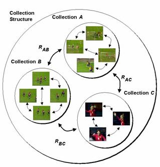
The Model DSs provide tools for modeling the attributes and features of audio-visual content. The Probability Model DS provides fundamental DSs for specifying different statistical functions and probabilistic structures. The Probability Model DS can be used for representing samples of audio-visual data and classes of Descriptors using statistical approximation.
The Analytic Model DSs describe collections of examples of audio-visual data or clusters of Descriptors that provide models for particular semantic classes. The Analytic Model DS specifies semantic labels that indicate the classes being modeled. The Analytic Model DSs also optionally specify the confidence in which the semantic labels are assigned to the models. Further built from the analytic models in MPEG-7 are classifiers. The Classifier DSs describe different types of classifiers that are used to assign semantic labels to audio-visual data based.
The UserInteraction DS describe preferences of users pertaining to the consumption of the AV content, as well as usage history. The MPEG-7 AV content descriptions can be matched to the preference descriptions in order to select and personalize AV content for more efficient and effective access, presentation and consumption. The UserPreference DS describes preferences for different types of content and modes of browsing, including context dependency in terms of time and place. The UserPreference DS describes also the weighting of the relative importance of different preferences, the privacy characteristics of the preferences and whether preferences are subject to update, such as by an agent that automatically learns through interaction with the user. The UsageHistory DS describes the history of actions carried out by a user of a multimedia system. The usage history descriptions can be exchanged between consumers, their agents, content providers, and devices, and may in turn be used to determine the user preferences with regard to AV content.
MPEG-7 Visual Description Tools included in the standard consist of basic structures and Descriptors that cover the following basic visual features: Color, Texture, Shape, Motion, Localization, and Face recognition. Each category consists of elementary and sophisticated Descriptors.
There are five Visual related Basic structures: the Grid layout, and the Time series, Multiple view, the Spatial 2D coordinates, and Temporal interpolation.
The grid layout is a splitting of the image into a set of equally sized rectangular regions, so that each region can be described separately. Each region of the grid can be described in terms of other Descriptors such as color or texture. Furthermore, the descriptor allows to assign the subDescriptors to all rectangular areas, as well as to an arbitrary subset of rectangular regions.
This descriptor defines a temporal series of Descriptors in a video segment and provides image to video-frame matching and video-frames to video-frames matching functionalities. Two types of TimeSeries are available: RegularTimeSeries and IrregularTimeSeries. In the former, Descriptors locate regularly (with constant intervals) within a given time span. This enables a simple representation for the application that requires low complexity. On the other hand, Descriptors locate irregularly (with various intervals) within a given time span in the latter. This enables an efficient representation for the application that has the requirement of narrow transmission bandwidth or low storage capability. These are useful in particular to build Descriptors that contain time series of Descriptors.
The 2D/3D Descriptor specifies a structure which combines 2D Descriptors representing a visual feature of a 3D object seen from different view angles. The descriptor forms a complete 3D view-based representation of the object. Any 2D visual descriptor, such as for example contour-shape, region-shape, colour or texture can be used. The 2D/3D descriptor supports integration of the 2D Descriptors used in the image plane to describe features of the 3D (real world) objects. The descriptor allows the matching of 3D objects by comparing their views, as well as comparing pure 2D views to 3D objects.
This description defines a 2D spatial coordinate system and a unit to be used by reference in other Ds/DSs when relevant. The coordinate system is defined by a mapping between an image and the coordinate system. One of the advantages using this descriptor is that MPEG-7 descriptions need not to be modified even if the image size is changed or a part of the image is clipped. In this case, only the description of the mapping from the original image to the edited image is required.
It supports two kinds of coordinate systems: "local" and "integrated" (see Figure 20). In a "local" coordinate system, the coordinates used for the calculation of the description is mapped to the current coordinate system applicable. In an "integrated" coordinate system, each image (frame) of e.g. a video may be mapped to different areas with respect to the first frame of a shot or video. The integrated coordinate system can for instance be used to represent coordinates on a mosaic of a video shot.

a) "Local" coordinates b) "Integrated" coordinates
The TemporalInterpolation D describes a temporal interpolation using connected polynomials. This can be used to approximate multi-dimensional variable values that change with time—such as an object position in a video. The description size of the temporal interpolation is usually much smaller than describing all values. In Figure 21, 25 real values are represented by five linear interpolation functions and two quadratic interpolation functions. The beginning of the temporal interpolation is always aligned to time 0.
There are seven Color Descriptors: Color space, Color Quantization, Dominant Colors, Scalable Color, Color Layout, Color-Structure, and GoF/GoP Color.
The feature is the color space that is to be used in other color based descriptions.
In the current description, the following color spaces are supported:
· Linear transformation matrix with reference to R, G, B
This descriptor defines a uniform quantization of a color space. The number of bins which the quantizer produces is configurable, such that great flexibility is provided for a wide range of applications. For a meaningful application in the context of MPEG-7, this descriptor has to be combined with dominant color descriptors, e.g. to express the meaning of the values of dominant colors.
This color descriptor is most suitable for representing local (object or image region) features where a small number of colors are enough to characterize the color information in the region of interest. Whole images are also applicable, for example, flag images or color trademark images. Color quantization is used to extract a small number of representing colors in each region/image. The percentage of each quantized color in the region is calculated correspondingly. A spatial coherency on the entire descriptor is also defined, and is used in similarity retrieval.
The Scalable Color Descriptor is a Color Histogram in HSV Color Space, which is encoded by a Haar transform. Its binary representation is scalable in terms of bin numbers and bit representation accuracy over a broad range of data rates. The Scalable Color Descriptor is useful for image-to-image matching and retrieval based on color feature. Retrieval accuracy increases with the number of bits used in the representation.
This descriptor effectively represents the spatial distribution of color of visual signals in a very compact form. This compactness allows visual signal matching functionality with high retrieval efficiency at very small computational costs. It provides image-to-image matching as well as ultra high-speed sequence-to-sequence matching, which requires so many repetitions of similarity calculations. It also provides very friendly user interface using hand-written sketch queries since this descriptors captures the layout information of color feature. The sketch queries are not supported in other color descriptors.
The advantages of this descriptor are:
· that there are no dependency on image/video format, resolutions, and bit-depths. The descriptor can be applied to any still pictures or video frames even though their resolutions are different. It can be also applied both to a whole image and to any connected or unconnected parts of an image with arbitrary shapes.
· that the required hardware/software resources for the descriptor is very small. It needs as law as 8 bytes per image in the default video frame search, and the calculation complexity of both extraction and matching is very low. It is feasible to apply this descriptor to mobile terminal applications where the available resources is strictly limited due to hardware constrain.
· that the captured feature is represented in frequency domain, so that users can easily introduce perceptual sensitivity of human vision system for similarity calculation.
· that it supports scalable representation of the feature by controlling the number of coefficients enclosed in the descriptor. The user can choose any representation granularity depending on their objectives without interoperability problems in measuring the similarity among the descriptors with different granularity. The default number of coefficients is 12 for video frames while 18 coefficients are also recommended for still pictures to achieve a higher accuracy.
The Color structure descriptor is a color feature descriptor that captures both color content (similar to a color histogram) and information about the structure of this content. Its main functionality is image-to-image matching and its intended use is for still-image retrieval, where an image may consist of either a single rectangular frame or arbitrarily shaped, possibly disconnected, regions. The extraction method embeds color structure information into the descriptor by taking into account all colors in a structuring element of 8x8 pixels that slides over the image, instead of considering each pixel separately. Unlike the color histogram, this descriptor can distinguish between two images in which a given color is present in identical amounts but where the structure of the groups of pixels having that color is different in the two images. Color values are represented in the double-coned HMMD color space, which is quantized non-uniformly into 32, 64, 128 or 256 bins. Each bin amplitude value is represented by an 8-bit code. The Color Structure descriptor provides additional functionality and improved similarity-based image retrieval performance for natural images compared to the ordinary color histogram.
The Group of Frames/Group of Pictures color descriptor extends the ScalableColor descriptor that is defined for a still image to color description of a video segment or a collection of still images. Additional two bits allows to define how the color histogram was calculated, before the Haar transfor is applied to it: by average, median or intersection. The average histogram, which refers to averaging the counter value of each bin across all frames or pictures, is equivalent to computing the aggregate color histogram of all frames and pictures with proper normalization. The Median Histogram refers to computing the median of the counter value of each bin across all frames or pictures. It is more robust to round-off errors and the presence of outliers in image intensity values compared to the average histogram. The Intersection Histogram refers to computing the minimum of the counter value of each bin across all frames or pictures to capture the "least common" color traits of a group of images. Note that it is different from the histogram intersection, which is a scalar measure. The same similarity/distance measures that are used to compare scalable color descriptions can be employed to compare GoF/GoP color Descriptors.
There are three texture Descriptors: Homogeneous Texture, Edge Histogram, and Texture Browsing.
Homogeneous texture has emerged as an important visual primitive for searching and browsing through large collections of similar looking patterns. An image can be considered as a mosaic of homogeneous textures so that these texture features associated with the regions can be used to index the image data. For instance, a user browsing an aerial image database may want to identify all parking lots in the image collection. A parking lot with cars parked at regular intervals is an excellent example of a homogeneous textured pattern when viewed from a distance, such as in an Air Photo. Similarly, agricultural areas and vegetation patches are other examples of homogeneous textures commonly found in aerial and satellite imagery. Examples of queries that could be supported in this context could include "Retrieve all Land-Satellite images of Santa Barbara which have less than 20% cloud cover" or "Find a vegetation patch that looks like this region". To support such image retrieval, an effective representation of texture is required. The Homogeneous Texture Descriptor provides a quantitative representation using 62 numbers (quantified to 8 bits each) that is useful for similarity retrieval. The extraction is done as follows; the image is first filtered with a bank of orientation and scale tuned filters (modeled using Gabor functions) using Gabor filters. The first and the second moments of the energy in the frequency domain in the corresponding sub-bands are then used as the components of the texture descriptor. The number of filters used is 5x6 = 30 where 5 is the number of "scales" and 6 is the number of "directions" used in the multi-resolution decomposition using Gabor functions. An efficient implementation using projections and 1-D filtering operations exists for feature extraction. The Homogeneous Texture descriptor provides a precise quantitative description of a texture that can be used for accurate search and retrieval in this respect. The computation of this descriptor is based on filtering using scale and orientation selective kernels.
The Texture Browsing Descriptor is useful for representing homogeneous texture for browsing type applications, and requires only 12 bits (maximum). It provides a perceptual characterization of texture, similar to a human characterization, in terms of regularity, coarseness and directionality. The computation of this descriptor proceeds similarly as the Homogeneous Texture Descriptor. First, the image is filtered with a bank of orientation and scale tuned filters (modeled using Gabor functions); from the filtered outputs, two dominant texture orientations are identified. Three bits are used to represent each of the dominant orientations. This is followed by analyzing the filtered image projections along the dominant orientations to determine the regularity (quantified to 2 bits) and coarseness (2 bits x 2). The second dominant orientation and second scale feature are optional. This descriptor, combined with the Homogeneous Texture Descriptor, provide a scalable solution to representing homogeneous texture regions in images.
The edge histogram descriptor represents the spatial distribution of five types of edges, namely four directional edges and one non-directional edge. Since edges play an important role for image perception, it can retrieve images with similar semantic meaning. Thus, it primarily targets image-to-image matching (by example or by sketch), especially for natural images with non-uniform edge distribution. In this context, the image retrieval performance can be significantly improved if the edge histogram descriptor is combined with other Descriptors such as the color histogram descriptor. Besides, the best retrieval performances considering this descriptor alone are obtained by using the semi-global and the global histograms generated directly from the edge histogram descriptor as well as the local ones for the matching process.
There are three shape Descriptors: Region Shape, Contour Shape, and Shape 3D.
The shape of an object may consist of either a single region or a set of regions as well as some holes in the object as illustrated in Figure 22. Since the Region Shape descriptor makes use of all pixels constituting the shape within a frame, it can describe any shapes, i.e. not only a simple shape with a single connected region as in Figure 22 (a) and (b) but also a complex shape that consists of holes in the object or several disjoint regions as illustrated in Figure 22 (c), (d) and (e), respectively. The Region Shape descriptor not only can describe such diverse shapes efficiently in a single descriptor, but is also robust to minor deformation along the boundary of the object.
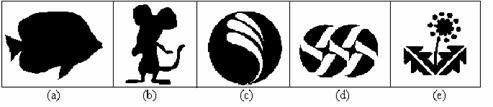
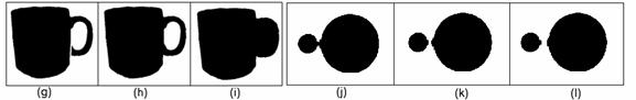
Figure 22 (g), (h) and (i) are very similar shape images for a cup. The differences are at the handle. Shape (g) has a crack at the lower handle while the handle in (i) is filled. The region-based shape descriptor considers (g) and (h) similar but different from (i) because the handle is filled. Similarly, Figure 22 (j-l) show the part of video sequence where two disks are being separated. With the region-based descriptor, they are considered similar.
Note that black pixel within the object corresponds to 1 in an image, while white background corresponds to 0.
The descriptor is also characterized by its small size, fast extraction time and matching. The data size for this representation is fixed to 17.5 bytes. The feature extraction and matching processes are straightforward to have low order of computational complexities, and suitable for tracking shapes in the video data processing.
The Contour Shape descriptor captures characteristic shape features of an object or region based on its contour. It uses so-called Curvature Scale-Space representation, which captures perceptually meaningful features of the shape.
The object contour-based shape descriptor is based on the Curvature Scale Space representation of the contour. This representation has a number of important properties, namely:
· It captures very well characteristic features of the shape, enabling similarity-based retrieval
· It reflects properties of the perception of human visual system and offers good generalization
· It is robust to non-rigid motion
· It is robust to partial occlusion of the shape
· It is robust to perspective transformations, which result from the changes of the camera parameters and are common in images and video
Some of the above properties of this descriptor are illustrated in Figure 23, each frame containing very similar images according to CSS, based on the actual retrieval results from the MPEG-7 shape database.
Considering the continuous development of multimedia technologies, virtual worlds, and augmented reality, 3D contents become a common feature of today information systems. Most of the time, 3D information is represented as polygonal meshes. MPEG-4, within the SNHC subgroup, considered this issue and developed technologies for efficient 3D mesh model coding. Within the framework of the MPEG-7 standard, tools for intelligent content-based access to 3D information are needed. The main MPEG-7 applications targeted here are search & retrieval and browsing of 3D model databases.
The 3D Shape Descriptor described in detail provides an intrinsic shape description of 3D mesh models. It exploits some local attributes of the 3D surface.
There are four motion Descriptors: Camera Motion, Motion Trajectory, Parametric Motion, and Motion Activity.
This descriptor characterizes 3-D camera motion parameters. It is based on 3-D camera motion parameter information, which can be automatically extracted or generated by capture devices.
The camera motion descriptor supports the following well-known basic camera operations (see Figure 24): fixed, panning (horizontal rotation), tracking (horizontal transverse movement, also called traveling in the film industry), tilting (vertical rotation), booming (vertical transverse movement), zooming (change of the focal length), dollying (translation along the optical axis), and rolling (rotation around the optical axis).


The sub-shots for which all frames are characterized by a particular type of camera motion, which can be single or mixed, determine the building blocks for the camera motion descriptor. Each building block is described by its start time, the duration, the speed of the induced image motion, by the fraction of time of its duration compared with a given temporal window size, and the focus-of-expansion (FOE) (or focus-of-contraction – FOC). The Descriptor represents the union of these building blocks, and it has the option of describing a mixture of different camera motion types. The mixture mode captures the global information about the camera motion parameters, disregarding detailed temporal information, by jointly describing multiple motion types, even if these motion types occur simultaneously. On the other hand, the non-mixture mode captures the notion of pure motion type and their union within certain time interval. The situations where multiple motion types occur simultaneously are described as a union of the description of pure motion types. In this mode of description, the time window of a particular elementary segment can overlap with time window of another elementary segment.
The motion trajectory of an object is a simple, high level feature, defined as the localization, in time and space, of one representative point of this object.
This descriptor shows usefulness for content-based retrieval in object-oriented visual databases. It is also of help in more specific applications. In given contexts with a priori knowledge, trajectory can enable many functionalities. In surveillance, alarms can be triggered if some object has a trajectory identified as dangerous (e.g. passing through a forbidden area, being unusually quick, etc.). In sports, specific actions (e.g. tennis rallies taking place at the net) can be recognized. Besides, such a description also allows enhancing data interactions/manipulations: for semiautomatic multimedia editing, trajectory can be stretched, shifted, etc, to adapt the object motion to any given sequence global context.
The descriptor is essentially a list of keypoints (x,y,z,t) along with a set of optional interpolating functions that describe the path of the object between keypoints, in terms of acceleration. The speed is implicitly known by the keypoints specification. The keypoints are specified by their time instant and either their 2-D or 3-D Cartesian coordinates, depending on the intended application. The interpolating functions are defined for each component x(t), y(t), and z(t) independently.
Some of the properties of this representation are that:
· it is independent of the spatio-temporal resolution of the content (e.g., 24 Hz, 30 Hz, 50 Hz, CIF, SIF, SD, HD, etc.), i.e. if the content exists in multiple formats simultaneously, only one set of Descriptors is needed to describe an object trajectory in all instances of that content.
· it is compact and scalable. Instead of storing object coordinate for each frame, the granularity of the descriptor is chosen through the number of keypoints used for each time interval. Besides, interpolating function-data may be discarded, as keypoint-data are already a trajectory description.
· it directly allows wide varieties of uses, like similarity search, or categorization by speed (fast, slow objects), behavior (accelerating when approaching this area) or by other high level motion characteristics.
Parametric motion models have been extensively used within various related image processing and analysis areas, including motion-based segmentation and estimation, global motion estimation, mosaicing and object tracking. Parametric motion models have been already used in MPEG-4, for global motion estimation and compensation and sprite generation. Within the MPEG-7 framework, motion is a highly relevant feature, related to the spatio-temporal structure of a video and concerning several MPEG-7 specific applications, such as storage and retrieval of video databases and hyperlinking purposes. Motion is also a crucial feature for some domain specific applications that have already been considered within the MPEG-7 framework, such as sign language indexation.
The basic underlying principle consists of describing the motion of objects in video sequences as a 2D parametric model. Specifically, affine models include translations, rotations, scaling and combination of them, planar perspective models make possible to take into account global deformations associated with perspective projections and quadratic models makes it possible to describe more complex movements.
The parametric model is associated with arbitrary (foreground or background) objects, defined as regions (group of pixels) in the image over a specified time interval. In this way, the object motion is captured in a compact manner as a set of a few parameters. Such an approach leads to a very efficient description of several types of motions, including simple translations, rotations and zoomings, or more complex motions such as combinations of the above-mentioned elementary motions.
Defining appropriate similarity measures between motion models is mandatory for effective motion-based object retrieval. It is also necessary for supporting both low level queries, useful in query by example scenarios, and high level queries such as "search for objects approaching the camera", or for "objects describing a rotational motion", or "search for objects translating left", etc.
A human watching a video or animation sequence perceives it as being a slow sequence, fast paced sequence, action sequence etc. The activity descriptor captures this intuitive notion of ‘intensity of action’ or ‘pace of action’ in a video segment. Examples of high ‘activity’ include scenes such as ‘goal scoring in a soccer match’, ‘scoring in a basketball game’, ‘a high speed car chase’ etc.. On the other hand scenes such as ‘news reader shot’, ‘an interview scene’, ‘a still shot’ etc. are perceived as low action shots. Video content in general spans the gamut from high to low activity, therefore we need a descriptor that enables us to accurately express the activity of a given video sequence/shot and comprehensively covers the aforementioned gamut. The activity descriptor is useful for applications such as video re-purposing, surveillance, fast browsing, dynamic video summarization, content-based querying etc. For example, we could slow down the presentation frame rate if the activity descriptor indicates high activity so as to make the high activity viewable. Another example of an application is finding all the high action shots in a news video program for example, which can be viewed both as browsing and abstraction.
There two descriptors for localization: Region locator and Spatio-temporal locator
This descriptor enables localization of regions within images or frames by specifying them with a brief and scalable representation of a Box or a Polygon.
This describes spatio-temporal regions in a video sequence, such as moving object regions, and provides localization functionality. The main application of it is hypermedia, which displays the related information when the designated point is inside the object. Another main application is object retrieval by checking whether the object has passed particular points. This can be used for surveillance. The SpatioTemporalLocator can describe both spatially connected and non-connected regions.

The FaceRecognition descriptor can be used to retrieve face images which match a query face image. The descriptor represents the projection of a face vector onto a set of basis vectors which span the space of possible face vectors. The FaceRecognition feature set is extracted from a normalized face image. This normalized face image contains 56 lines with 46 intensity values in each line. The centers of the two eyes in each face image are located on the 24th row and the 16th and 31st column for the right and left eye respectively. This normalized image is then used to extract the one dimensional face vector which consists of the luminance pixel values from the normalized face image arranged into a one dimensional vector using a raster scan starting at the top-left corner of the image and finishing at the bottom-right corner of the image. The FaceRecogniton feature set is then calculated by projecting the one dimensional face vector onto the space defined by a set of basis vectors.
MPEG-7 Audio provides structures—building upon some basic structures from the MDS—for describing audio content. Utilizing those structures are a set of low-level Descriptors, for audio features that cut across many applications (e.g., spectral, parametric, and temporal features of a signal), and high-level Description Tools that are more specific to a set of applications. Those high-level tools include the audio signature Description Scheme, musical instrument timbre Description Schemes, the melody Description Tools to aid query-by-humming, general sound recognition and indexing Description Tools, and spoken content Description Tools.
The Audio Framework contains low-level tools designed to provide a basis for the construction of higher level audio applications. By providing a common platform for the structure of descriptions and the basic semantics for commonly regarded audio features, MPEG-7 Audio establishes a platform for interoperability across all applications that might be built on the framework. The framework provides structures appropriate for representing audio features, and a basic set of features.
There are essentially two ways of describing low-level audio features. One may sample values at regular intervals or one may use Segments (see the discussion on segments in 3.1.1.3) to demark regions of similarity and dissimilarity within the sound. Both of these possibilities are embodied in two low-level descriptor types (one for scalar values, such as power or fundamental frequency, and one for vector types, such as spectra), which create a consistent interface. Any descriptor inheriting from these types can be instantiated, describing a segment with a single summary value or a series of sampled values, as the application requires.
The sampled values themselves may be further manipulated through another unified interface: they can form a Scalable Series. The Scalable Series allows one to progressively down-sample the data contained in a series, as the application, bandwidth, or storage requires. This hierarchical resampling forms a sort of ‘scale tree,’ which may also store various summary values along the way, such as minimum, maximum, mean, and variance of the descriptor values.
The low-level audio Descriptors are of general importance in describing audio. There are seventeen temporal and spectral Descriptors that may be used in a variety of applications. They can be roughly divided into the following groups:
Additionally, a very simple but useful tool is the MPEG-7 silence Descriptor. Each of these classes of audio Descriptors can be seen in Figure 26 and are briefly described below.
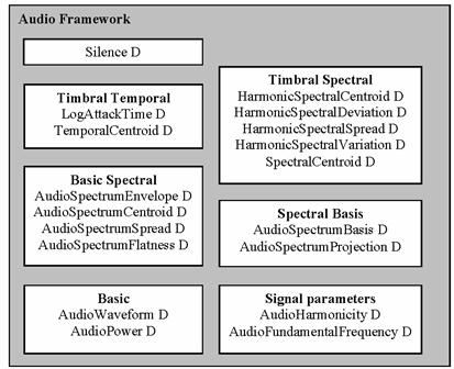
The two basic audio Descriptors are temporally sampled scalar values for general use, applicable to all kinds of signals. The AudioWaveform Descriptor describes the audio waveform envelope (minimum and maximum), typically for display purposes. The AudioPower Descriptor describes the temporally-smoothed instantaneous power, which is useful as a quick summary of a signal, and in conjunction with the power spectrum, below.
The four basic spectral audio Descriptors all share a common basis, all deriving from a single time-frequency analysis of an audio signal. They are all informed by the first Descriptor, the AudioSpectrumEnvelope Descriptor, which is a logarithmic-frequency spectrum, spaced by a power-of-two divisor or multiple of an octave. This AudioSpectrumEnvelope is a vector that describes the short-term power spectrum of an audio signal. It may be used to display a spectrogram, to synthesize a crude "auralization" of the data, or as a general-purpose descriptor for search and comparison.
The AudioSpectrumCentroid Descriptor describes the center of gravity of the log-frequency power spectrum. This Descriptor is an economical description of the shape of the power spectrum, indicating whether the spectral content of a signal is dominated by high or low frequencies. The AudioSpectrumSpread Descriptor complements the previous Descriptor by describing the second moment of the log-frequency power spectrum, indicating whether the power spectrum is centered near the spectral centroid, or spread out over the spectrum. This may help distinguish between pure-tone and noise-like sounds.
The AudioSpectrumFlatness Descriptor describes the flatness properties of the spectrum of an audio signal for each of a number of frequency bands. When this vector indicates a high deviation from a flat spectral shape for a given band, it may signal the presence of tonal components.
The two signal parameter Descriptors apply chiefly to periodic or quasi-periodic signals. The AudioFundamentalFrequency descriptor describes the fundamental frequency of an audio signal. The representation of this descriptor allows for a confidence measure in recognition of the fact that the various extraction methods, commonly called "pitch-tracking," are not perfectly accurate, and in recognition of the fact that there may be sections of a signal (e.g., noise) for which no fundamental frequency may be extracted. The AudioHarmonicity Descriptor represents the harmonicity of a signal, allowing distinction between sounds with a harmonic spectrum (e.g., musical tones or voiced speech [e.g., vowels]), sounds with an inharmonic spectrum (e.g., metallic or bell-like sounds) and sounds with a non-harmonic spectrum (e.g., noise, unvoiced speech [e.g., fricatives like ‘f’], or dense mixtures of instruments).
The two timbral temporal Descriptors describe temporal characteristics of segments of sounds, and are especially useful for the description of musical timbre (characteristic tone quality independent of pitch and loudness). Because a single scalar value is used to represent the evolution of a sound or an audio segment in time, these Descriptors are not applicable for use with the Scalable Series. The LogAttackTime Descriptor characterizes the "attack" of a sound, the time it takes for the signal to rise from silence to the maximum amplitude. This feature signifies the difference between a sudden and a smooth sound. The TemporalCentroid Descriptor also characterizes the signal envelope, representing where in time the energy of a signal is focused. This Descriptor may, for example, distinguish between a decaying piano note and a sustained organ note, when the lengths and the attacks of the two notes are identical.
The five timbral spectral Descriptors are spectral features in a linear-frequency space especially applicable to the perception of musical timbre. The SpectralCentroid Descriptor is the power-weighted average of the frequency of the bins in the linear power spectrum. As such, it is very similar to the AudioSpectrumCentroid Descriptor, but specialized for use in distinguishing musical instrument timbres. It is has a high correlation with the perceptual feature of the "sharpness" of a sound.
The four remaining timbral spectral Descriptors operate on the harmonic regularly-spaced components of signals. For this reason, the descriptors are computed in linear-frequency space. The HarmonicSpectralCentroid is the amplitude-weighted mean of the harmonic peaks of the spectrum. It has a similar semantic to the other centroid Descriptors, but applies only to the harmonic (non-noise) parts of the musical tone. The HarmonicSpectralDeviation Descriptor indicates the spectral deviation of log-amplitude components from a global spectral envelope. The HarmonicSpectralSpread describes the amplitude-weighted standard deviation of the harmonic peaks of the spectrum, normalized by the instantaneous HarmonicSpectralCentroid. The HarmonicSpectralVariation Descriptor is the normalized correlation between the amplitude of the harmonic peaks between two subsequent time-slices of the signal.
The two spectral basis Descriptors represent low-dimensional projections of a high-dimensional spectral space to aid compactness and recognition. These descriptors are used primarily with the Sound Classification and Indexing Description Tools, but may be of use with other types of applications as well. The AudioSpectrumBasis Descriptor is a series of (potentially time-varying and/or statistically independent) basis functions that are derived from the singular value decomposition of a normalized power spectrum. The AudioSpectrumProjection Descriptor is used together with the AudioSpectrumBasis Descriptor, and represents low-dimensional features of a spectrum after projection upon a reduced rank basis.
Together, the descriptors may be used to view and to represent compactly the independent subspaces of a spectrogram. Often these independent subspaces (or groups thereof) correlate strongly with different sound sources. Thus one gets more salience and structure out of a spectrogram while using less space. For example, in Figure 27, a pop song is represented by an AudioSpectrumEnvelope Descriptor, and visualized using a spectrogram. The same song has been data-reduced in Figure 28, and yet the individual instruments become more salient in this representation.
The silence segment simply attaches the simple semantic of "silence" (i.e. no significant sound) to an Audio Segment. Although it is extremely simple, it is a very effective descriptor. It may be used to aid further segmentation of the audio stream, or as a hint not to process a segment.
Because there is a smaller set of audio features (as compared to visual features) that may canonically represent a sound without domain-specific knowledge, MPEG-7 Audio includes a set of specialized high-level tools that exchange some degree of generality for descriptive richness. The five sets of audio Description Tools that roughly correspond to application areas are integrated in the standard: audio signature, musical instrument timbre, melody description, general sound recognition and indexing, and spoken content. The latter two are excellent examples of how the Audio Framework and MDS Description Tools may be integrated to support other applications.
While low-level audio Descriptors in general can serve many conceivable applications, the spectral flatness Descriptor specifically supports the functionality of robust matching of audio signals. The Descriptor is statistically summarized in the AudioSignature Description Scheme as a condensed representation of an audio signal designed to provide a unique content identifier for the purpose of robust automatic identification of audio signals. Applications include audio fingerprinting, identification of audio based on a database of known works and, thus, locating metadata for legacy audio content without metadata annotation.
Timbre Descriptors aim at describing perceptual features of instrument sounds. Timbre is currently defined in the literature as the perceptual features that make two sounds having the same pitch and loudness sound different. The aim of the Timbre Description Tools is to describe these perceptual features with a reduced set of Descriptors. The Descriptors relate to notions such as "attack", "brightness" or "richness" of a sound.
Within four possible classes of musical instrument sounds, two classes are well detailed, and had been the subject of extensive development within MPEG-7. Harmonic, coherent, sustained sounds, and non-sustained, percussive sounds are represented in the standard. The HarmonicInstrumentTimbre Descriptor for sustained harmonic sounds combines the four harmonic timbral spectral Descriptors (see 3.3.1.7) with the LogAttackTime Descriptor. The PercussiveIinstrumentTimbre Descriptor combines the timbral temporal Descriptors (see 3.3.1.6) with a SpectralCentroid Descriptor. Comparisons between descriptions using either set of Descriptors are done with an experimentally-derived scaled distance metric.
The melody Description Tools include a rich representation for monophonic melodic information to facilitate efficient, robust, and expressive melodic similarity matching. The Melody Description Scheme includes a MelodyContour Description Scheme for extremely terse, efficient melody contour representation, and a MelodySequence Description Scheme for a more verbose, complete, expressive melody representation. Both tools support matching between melodies, and can support optional supporting information about the melody that may further aid content-based search, including query-by-humming.
The MelodyContour Description Scheme uses a 5-step contour (representing the interval difference between adjacent notes), in which intervals are quantized into large or small intervals, up, down, or the same. The Melody Contour DS also represents basic rhythmic information by storing the number of the nearest whole beat of each note, which can dramatically increase the accuracy of matches to a query.
For applications requiring greater descriptive precision or reconstruction of a given melody, the MelodySequence Description Scheme supports an expanded descriptor set and high precision of interval encoding. Rather than quantizing to one of five levels, the precise pitch interval (to cent or greater precision) between notes is kept. Precise rhythmic information is kept by encoding the logarithmic ratio of differences between the onsets of notes in a manner similar to the pitch interval. Arrayed about these core Descriptors are a series of optional support Descriptors such as lyrics, key, meter, and starting note, to be used as desired by an application.
The general sound recognition and indexing Description Tools are a collection of tools for indexing and categorization of general sounds, with immediate application to sound effects. The tools enable automatic sound identification and indexing, and the specification of a Classification Scheme of sound classes and tools for specifying hierarchies of sound recognizers. Such recognizers may be used to automatically index and segment sound tracks. Thus the Description Tools address recognition and representation all the way from low-level signal-based analyses, through mid-level statistical models, to highly semantic labels for sound classes.
The recognition tools use the low-level spectral basis Descriptors as their foundation (see 3.3.1.8). These basis functions are then collected into a series of states that comprise a statistical model (the SoundModel Description Scheme), such as a hidden Markov or Gaussian mixture model. The SoundClassificationModel Description Scheme combines a set of SoundModels into a multi-way classifier for automatic labelling of audio segments using terms from a Classification Scheme. The resulting probabilistic classifiers may recognize broad sounds classes, such as speech and music, or they can be trained to identify narrower categories such as male, female, trumpet, or violin. Other applications include genre classification and voice recognition.
A SoundModelStatePath Descriptor consists of a sequence of indices to states generated by a SoundModel, given an audio segment. This simple Descriptor provides a compact description of a sound segment, and can be used for quick comparisons with other models. The SoundModelStateHistogram Descriptor consists of a normalized histogram of the state sequence generated by a SoundModel. The descriptor may be used to compare sound segments via their histograms of their state activation patterns.
The spoken content Description Tools allow detailed description of words spoken within an audio stream. In recognition of the fact that current Automatic Speech Recognition (ASR) technologies have their limits, and that one will always encounter out-of-vocabulary utterances, the spoken content Description Tools sacrifice some compactness for robustness of search. To accomplish this, the tools represent the output and what might normally be seen as intermediate results of Automatic Speech Recognition (ASR). The tools can be used for two broad classes of retrieval scenario: indexing into and retrieval of an audio stream, and indexing of multimedia objects annotated with speech.
The Spoken Content Description Tools are divided into two broad functional units: the SpokenContentLattice Description Scheme, which represents the actual decoding produced by an ASR engine, and the SpokenContentHeader, which contains information about the speakers being recognized and the recognizer itself.
The SpokenContentHeader contains a number of components that are usable by any SpokenContentLattice. The header contains a WordLexicon Descriptor and a PhoneLexicon Descriptor, the former being an indexed list of tokens representing the repertoire of words of a recognizer, and the latter being the repertoire of phonetic components for a recognizer. There may be a ConfusionInfo Descriptor, which provides a confusion matrix and other insertion and deletion statistics for each entry in the PhoneLexicon. There must be a SpeakerInfo Descriptor, which conveys information about the person speaking in the audio, such as their vocabulary and phonetic repertoire, a characterization of their common speaking habits (ConfusionInfo), the language they’re speaking, and information about them as a person (inherited from MDS PersonType) such as their name. Additionally, within the SpokenContentHeader, there may be additional information on how the description was generated.
The SpokenContentLattice Description Scheme consists blocks of nodes. Nodes are connected by WordLinks or PhoneLinks, each of which links refers to a word or phone in the lexicon. Nodes are also indexed and are given a timeOffset from the beginning of the lattice. This highly flexible, but relatively compact, description format thus allows one to represent utterances with combinations of alternatives between words and phonemes. By combining these lattices, the problem of out-of-vocabulary words is greatly alleviated and retrieval may still be carried out when the original word recognition was in error. A simplified SpokenContentLattice is depicted in Figure 29.
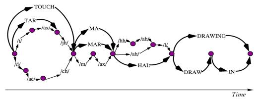
Example applications for the spoken content Description Tools include:
· Recall of audio/video data by memorable spoken events. An example would be a film or video recording where a character or person spoke a particular word or sequence of words. The source media would be known, and the query would return a position in the media.
· Spoken Document Retrieval. In this case, there is a database consisting of separate spoken documents. The result of the query is the relevant documents, and optionally the position in those documents of the matched speech.
· Annotated Media Retrieval. This is similar to spoken document retrieval, but the spoken part of the media would generally be quite short (a few seconds). The result of the query is the media which is annotated with speech, and not the speech itself. An example is a photograph retrieved using a spoken annotation.
3.4 MPEG-7 Description Definition Language (DDL)
The main tools used to implement MPEG-7 descriptions are the Description Definition Language (DDL), Description Schemes (DSs), and Descriptors (Ds). Descriptors bind a feature to a set of values. Description Schemes are models of the multimedia objects and of the universes that they represent e.g. the data model of the description. They specify the types of the Descriptors that can be used in a given description, and the relationships between these Descriptors or between other Description Schemes
The DDL forms a core part of the MPEG-7 standard. It provides the solid descriptive foundation by which users can create their own Description Schemes and Descriptors. The DDL defines the syntactic rules to express and combine Description Schemes and Descriptors. According to the definition in the MPEG-7 Requirements Document the DDL is
‘...a language that allows the creation of new Description SchemesDescription Schemes and, possibly, DescriptorsDescriptors. It also allows the extension and modification of existing Description SchemesDescription Schemes.’
The DDL is not a modeling language such as Unified Modeling Language (UML) but a schema language to represent the results of modeling audiovisual data, i.e. DSs and Ds.
The DDL satisfies the MPEG-7 DDL requirements. It is able to express spatial, temporal, structural, and conceptual relationships between the elements of a DS, and between DSs. It provides a rich model for links and references between one or more descriptions and the data that it describes. In addition, it is platform and application independent and human- and machine-readable.
(Non-normative) DDL Parser applications will be required which are capable of validating description schemes (content and structure) and descriptor data types (both primitive (integer, text, date, time) and composite (histograms, enumerated types), against the DDL. The DDL Parsers must also be capable of validating MPEG-7 descriptions or instantiations, against their corresponding validated MPEG-7 schemas (DSs and Ds).
The DDL design has been informed by numerous proposals and input documents submitted to the MPEG-7 DDL AHG since the MPEG-7 Call for Proposals in October 1998. It has also been heavily influenced by W3C XML Schema Language and the Resource Description Framework (RDF).
At the 51st MPEG meeting in Noordwijkerhout in March 2000, it was decided to adopt XML Schema Language as the MPEG-7 DDL. However because XML Schema language has not been designed specifically for audiovisual content, certain extensions have been necessary in order to satisfy all of the MPEG-7 DDL requirements.
This overview presents the current status of the MPEG-7 Description Definition Language which is based on the XML Schema Recommendations published by the W3C in May 2001..
The purpose of a schema is to define a class of XML documents by specifying particular constructs that constrain the structure and content of the documents. Possible constraints include: elements and their content, attributes and their values, cardinalities and datatypes. XML Schemas provide a superset of the capabilities of DTDs.
The primary recommendation of the MPEG-7 community was that the DDL should be based on XML. Many solutions were available when the development started but none of them were considered sufficiently stable to provide a final solution. In April 2000, the W3C XML Schema Working Group published the Last Call Working Drafts of the XML Schema 1.0 specification. The improved stability of XML Schema Language, its potential wide-spread adoption, availability of tools and parsers and its ability to satisfy the majority of MPEG-7 requirements, led to the decision to adopt XML Schema as the basis for the DDL. However because XML Schema was not designed specifically for audiovisual content, certain specific MPEG-7 extensions were required. Consequently the DDL can be broken down into the following logical normative components:
· XML Schema Structural components;
· XML Schema Datatype components;
· MPEG-7 Extensions to XML Schema.
XML Schema: Structures is part 1 of the 2-part XML Schema specification. It provides facilities for describing the structure and constraining the content of XML 1.0 documents. An XML Schema consists of a set of structural schema components which can be divided into three groups. The primary components are:
· The Schema – the wrapper around the definitions and declarations;
· Element declarations.
· Attribute group definitions;
· Identity-constraint definitions;
The third group is composed by the "helper" components which contribute to the other components and cannot stand alone:
· Wildcards.
Type definitions define internal schema components which can be used in other schema components such as element or attribute declarations or other type definitions. XML Schema provides two kinds of type definition component :
· simple types – which are simple data types (built-in or derived) which cannot have any child elements or attributes;
· complex types – which may carry attributes and have children elements or be derived from other simple or complex types.
Elements and attributes can then be declared which have are of types. New types can also be defined by derivation from existing types (built-ins or derived) through an extension or restriction of the base type.
Precise details of the use and application of these components can be found in the DDL Specification, ISO/IEC 15938-2 or the XML Schema: Structures Specification.
XML Schema:Datatypes is part 2 of the 2-part XML Schema specification. It proposes facilities for defining datatypes to be used to constrain the datatypes of elements and attributes within XML Schemas. It provides a higher degree of type checking than is available within XML 1.0 DTDs.
· a set of built-in primitive datatypes;
· a set of built-in derived datatypes;
· mechanisms by which users can define their own derived datatypes.
A derived datatype can be defined from a primitive datatype or another derived datatype by adding constraining facets.
Precise details of the built-in datatypes and derivation mechanisms can be found in the DDL Specification, ISO/IEC 15938-2 or the XML Schema: Datatypes Specification.
The following features were added to the XML Schema Language specification in order to satisfy specific MPEG-7 requirements :
· Array and matrix datatypes – both fixed size and parameterized size;
· Built-in primitive time datatypes: basicTimePoint and basicDuration.
Precise details of the MPEG-7 extensions are available in the DDL Specification, ISO/IEC 15938-2.
MPEG-7-specific parsers have been developed by adding validation of these additional constructs to standard XML Schema parsers.
3.5 BiM (Binary Format for MPEG-7)
XML has not been designed to deal ideally in a real-time, constrained and streamed environment like in the multimedia or mobile industry. As long as structured documents (HTML, for instance) were basically composed of only few embedded tags, the overhead induced by textual representation was not critical. MPEG-7 standardizes an XML language for audiovisual metadata. MPEG-7 uses XML to model this rich and structured data. To overcome the lack of efficiency of textual XML, MPEG-7 Systems defines a generic framework to facilitate the carriage and processing of MPEG-7 descriptions: BiM (Binary Format for MPEG-7). It enables the streaming and the compression of any XML documents.
BiM coders and decoders can deal with any XML language. Technically, the schema definition (DTD or XML Schema) of the XML document is processed and used to generate a binary format. This binary format has two main properties. First, due to the schema knowledge, structural redundancy (element name, attribute names, aso) is removed from the document. Therefore the document structure is highly compressed (98% in average). Second, elements and attributes values are encoded according to some dedicated codecs. A library of basic datatype codecs is provided by the specification (IEEE 754, UTF_8, compact integers, VLC integers, lists of values, aso...). Other codecs can easily be plugged using the type-codec mapping mechanism defined in the standard.
One of the main technical advantages of the BiM binary encoding process is to be guided by schema information. In BiM, the schema is known both by the encoder and the decoder. This has several advantages compared to schema independent encoding scheme like WBXML or Zip or a specific encoding scheme.
First the binary format is deduced from the schema definition. There is no need to define coding tables or a specific encoding mechanism (like with the WBML encoding scheme). The binary format is inferred from the XML textual format. As a main result, very little extra work is needed to define the binary encoding of an XML language.
In a typical Internet use case, the terminal has to validate a received document to recover default values, exact namespace information, aso… BiM performs the validation at encoder side and sends the document in pre-parsed format. Therefore, when encoded, a document has already reached a very good level of validity. Very few extra processing is needed on the receiver side to validate the received document.
The validation process (performed by an XML validating parser) is used to associate a type information to every component of an XML document (attribute, element, leaf nodes), gives default values, aso. This mapping is performed at encoder side to improve compression ratio and to facilitate document processing. It is used to select the proper encoding scheme for each leaf of the XML document tree. The document values are therefore transmitted in a typed format and can directly be processed by the terminal without performing any string conversion (like the time consuming "atoi" function needed when working at textual level).
A BiM decoder can deal with evolution of XML languages. Technically, at encoding phase a level of compatibility is chosen for the bitstream. The encoding process adds necessary information to ensure that an old decoder will be able to skip unknown part of the bitstream. This feature allows also XML private extensions to be easily inserted within the original XML document without breaking interoperability. If forward compatibility is not needed, the redundancy is removed and the bitstream becomes more compact.
Each document can be transmitted in one or more pieces. At the lowest level of granularity, each attribute value or document leaf can be modified to allow a minimal transmission in case of a minimal change in the sent document, like depicted in Figure 30.
For instance, the streaming capability of BiM enables to cut a large XML document in many pieces. These pieces can be delivered separately to the client. It is not required for the decoder to download (and keep in memory) the entire XML file before being capable of processing it. It can reduce both memory required at terminal side and consumed bandwidth. It improves overall quality of service and response time of XML based services.
In a streamed environment, a single XML document can be maintained at terminal side by constantly refreshing its sub parts. Different refresh rate can be imposed to different sub part of the same XML document. This updating capability allows to finely manage consumed bandwidth and to provide the best quality of service for the minimal bandwidth consumption.
Unlike a zipped XML document, a BiM file can be processed directly at binary level. Moreover, document sub-trees can be skipped improving the overall performance of an application dealing with large documents. This optional "skipping" process can be triggered on the basis of element names, types or attribute values. This feature considerably improves browsing and searching through large XML files.

BiM is an open framework, which can receive, dedicated codec to better deal with specific domain constraints. For instance, BiM can receive quantification or zip compression algorithms.
MPEG-7 Systems provides the means to represent coded multimedia content descriptions. The entity that makes use of such coded representations of the multimedia content description is generically referred to as the "ISO/IEC 15938 terminal," "MPEG-7 terminal," or just "terminal" in short. This terminal may correspond to a standalone application or be part of an application system.
In Figure 32, there are three main architectural layers outlined: the application, the normative systems layer, and the delivery layer. MPEG-7 Systems is not concerned with any storage and/or transmission media (whose behaviours and characteristics are abstracted by the delivery layer) or the way the application processes the current description. The standard does make specific assumptions about the delivery layer, and those assumptions are outlined in 3.6.5.4. We describe the decoder architecture here in order to provide an overview.
3.6.2 General characteristics of the decoder
An MPEG-7 terminal consumes description streams and outputs a – potentially dynamic – representation of the description called the current description tree. Description streams consist of a sequence of individually accessible portions of data named Access Units. An Access Unit (AU) is the smallest data entity to which "terminal-oriented" timing information (as opposed to "described-media oriented" timing information, the kind of time specified in the MDS) can be attributed. This timing information is called the "composition" time, meaning the point in time when the resulting current description tree corresponding to a specific Access Unit becomes known to the application. The timing information is carried by the delivery layer (see 3.6.5.4). The current description tree is schema-valid after processing each access unit.
A description consisting of textual Access Units is called a textual description stream and is processed by a textual decoder (see 3.6.2.2). A description stream consisting of binary Access Units is called a binary description stream and is processed by a binary decoder (see 3.6.2.3). A mixture of both formats in a single stream is not permitted. The choice of either binary or textual format for the description stream is application dependent. Any valid MPEG-7 description, with the exception of those listed in 3.6.6.4, may be conveyed in either format.
3.6.2.2 Principles of the textual decoder
The MPEG-7 Systems method for textual encoding, called TeM, enables the dynamic and/or progressive transmission of descriptions using only text. The original description, in the form of an XML document, is partitioned into fragments (see 3.6.5.1) that are wrapped in further XML code so that these resulting AUs can be individually transported (e.g., streamed, or sent progressively). The decoding process for these AUs does not require any schema knowledge. The resulting current description tree may be byte-equivalent to the original description if desired by the encoder, but it may also exhibit dynamic characteristics such that certain parts of the description are present at the decoder only at chosen times, are never present at all, or appear in a different part of the tree.
3.6.2.3 Principles of the binary decoder
Using the MPEG-7 Systems generic method for binary encoding, called BiM, a description (nominally in a textual XML form) can be compressed, partitioned, streamed, and reconstructed at terminal side. The reconstructed XML description will not be byte-equivalent to the original description. Namely, the binary encoding method does not preserve processing instructions, attribute order, comments, or non-significant whitespace. However, the encoding process ensures that XML element order is preserved.
The BiM, in order to gain its compression efficiency, relies on a schema analysis phase. During this phase, internal tables are computed to associate binary code to XML elements, types and attributes. This principle mandates the full knowledge of the same schema by the decoder and the encoder for maximum interoperability.
As with the textual decoder, the resulting current description tree may be topologically equivalent to the original description if desired by the encoder, but it may also exhibit dynamic characteristics such that certain parts of the description are present at the decoder only at chosen times, are never present at all, or appear in a different part of the tree.
The decoder set-up is signaled by the initialization extractor receiving a textual or binary DecoderInit. The signaling of the use of either binary or textual encoding is outside the scope of this specification, but a binary DecoderInit results in the expectation of binary Access Units, and a textual DecoderInit results in textual Access Units. The DecoderInit is passed to the systems layer by the delivery layer. The DecoderInit will typically be conveyed by a separate delivery channel compared to the description stream, which is also received from the delivery layer. The component parts of the description stream are discussed in the following section.
The DecoderInit contains a list of URIs that identifies schemas, miscellaneous parameters to configure the decoder (FU Decoder Parameters, in Figure 32), and an Initial Description. There is only one DecoderInit per description stream. The list of URIs (Schema URIs, in Figure 32) is passed to a schema resolver that associates the URIs with schemas to be passed into the fragment update decoder. The schema resolver is non-normative and may, for example, retrieve schema documents from a network or refer to pre-stored schemas. The resulting schemas are used by the binary decoder and by any textual DDL parser that may be used for schema validation. If a given Schema URI is unknown to the schema resolver, the corresponding data types in a description stream are ignored.
The initial description has the same general syntax and semantics as an Access Unit, but with restrictions. The initial description initialises the current description tree without conveying it to the application. The current description tree is then updated by the Access Units that comprise the description stream. The initial description may be empty, since a schema-valid current description tree for consumption by the application need only be generated after the first Access Unit is decoded.
The description stream is processed only after the decoder is initialized. An Access Unit is composed of any number of Fragment Update Units, each of which is extracted in sequence by the fragment update component extractor. Each Fragment Update Unit consists of:
· a Fragment Update Command that specifies the type of update to be executed (i.e., add, replace or delete content or a node, or reset the current description tree);
· a Fragment Update Context that identifies the data type in a given schema document, and points to the location in the current description tree where the Fragment Update Command applies; and
· a Fragment Update Payload conveying the coded description fragment to be added or replaced.
A fragment update extractor splits the Fragment Update Units from the Access Units and emits the above component parts to the rest of the decoder. The fragment update command decoder generally consists of a simple table lookup for the update command to be passed on to the description composer. The decoded fragment update context information (‘context’ in Figure 32) is passed along to both the description composer and the fragment update payload decoder. The fragment update payload decoder embodies the BiM Payload decoder or, in the case of the TeM, a DDL parser, which decodes a Fragment Update Payload (aided by context information) to yield a description fragment (see Figure 32).
The corresponding update command and context are processed by the non-normative description composer, which either places the description fragment received from the fragment update payload decoder at the appropriate node of the current description tree at composition time, or sends a reconstruction event containing this information to the application. The actual reconstruction of the current description tree by the description composer is implementation-specific, i.e., the application may direct the description composer to prune or ignore unwanted elements as desired. There is no requirement on the format of this current description tree, e.g. it may remain a binary representation.
A description stream serves to convey a multimedia content description, as available from a (non-normative) sender or encoder, to the receiving terminal, possibly by incremental transmission in multiple Access Units. Any number of decompositions of the source description may be possible and it is out of scope of this specification to define such decompositions. Figure 33 illustrates an example of a description, consisting of a number of nodes, that is broken into two description fragments.
If multiple description fragments corresponding to a specific node of the description are sent (e.g., a node is replaced) then the previous data within the nodes of the description represented by that description fragment become unavailable to the terminal. Replacing a single node of the description effectively overwrites all children of that node.
3.6.5.2 Deferred nodes and their use
With both the TeM and the BiM, there exists the possibility for the encoder to indicate that a node in the current description tree is "Deferred." A deferred node does not contain content, but does have a type associated with it. A deferred node is addressable on the current description tree (there is a Fragment Update Context that unambiguously points to it), but it will not be passed on to any further processing steps, such as a parser or an application. In other words, a deferred node is a placeholder that is rendered "invisible" to subsequent processing steps.
The typical use of deferred nodes by the encoder is to establish a desired tree topology without sending all nodes of the tree. Nodes to be sent later are marked as "deferred" and are therefore hidden from a parser. Hence, the current description tree minus any deferred nodes must be schema-valid at the end of each Access Unit. The deferred nodes may then be replaced in any subsequent Access Unit without changing the tree topology maintained internally in the decoder. However, there is no guarantee that a deferred node will ever be filled by a subsequent fragment update unit within the description stream.
It is very conceivable that a given schema will be updated during its lifetime. Therefore, MPEG-7 Systems provides, with some constraints, interoperability between different versions of MPEG-7 schema definitions, without the full knowledge of all schema versions being required.
Two different forms of compatibility between different versions of schema are distinguished. In both cases, it is assumed that the updated version of a schema imports the previous version of that schema. Backward compatibility means that a decoder aware of an updated version of a schema is able to decode a description conformant to a previous version of that schema. Forward compatibility means that a decoder only aware of a previous version of a schema is able to partially decode a description conformant to an updated version of that schema.
With both the textual and binary format, backward compatibility is provided by the unique reference of the used schema in the DecoderInit using its Schema URI as its namespace identifier.
When using the binary format, forward compatibility is ensured by a specific syntax. Its main principle is to use the namespace of the schema, i.e., the Schema URI, as a unique version identifier. The binary format allows one to keep parts of a description related to different schema in separate chunks of the binary description stream, so that parts related to unknown schema may be skipped by the decoder. In order for this approach to work, an updated schema should not be defined using the DDL "redefine" construct but should be defined in a new namespace. The Decoder Initialisation identifies schema versions with which compatibility is preserved by listing their Schema URIs. A decoder that knows at least one of the Schema URIs will be able to decode at least part of the binary description stream.
The standard itself cannot guarantee reference (link) consistency in all cases. In particular, XPath-style references cannot be guaranteed to point to the correct node, especially when the topology of the tree changes in a dynamic or progressive transmission environment. With ID/IDRef, the system itself cannot guarantee that the ID element will be present, but during the validation phase, all such links are checked, and thus their presence falls under the directive that the current description tree must always be schema-valid. URI and HREF links are typically to external documents, and should be understood not to be under control by the referrer (and therefore not guaranteed).
BiM and TeM are two similar methods to fragment and convey descriptions as a description stream. While both methods allow one to convey arbitrary descriptions conformant to MPEG-7 MDS, Visual, and Audio, structural differences in the TeM- and BiM-encoded representation of the description as well as in the decoding process exist.
3.6.6.2 Use of schema knowledge
The TeM does not require schema knowledge to reconstitute descriptions; hence, the context information identifying the operand node on which the Fragment Update Command is applied is generated with reference to the current description tree as available to the decoder before processing the current fragment update. The TeM operates on an instantiation-based model: one begins with a blank slate (a single selector node) and adds instantiated nodes as they are presented to the terminal. Schema knowledge is, of course, necessary for schema validation to be performed.
The BiM relies upon schema knowledge, i.e., the FU decoder implicitly knows about the existence and position of all potential elements as defined by the schema, no matter whether the corresponding elements have actually been received in the instantiated description. This shared knowledge between encoder and decoder improves compression of the context information and makes the context information independent from the current description tree as available to the decoder. The BiM operates on a schema-based model: all possibilities defined by the schema can be unambiguously addressed using the context information, and as a payload is added, the instantiation of the addressed node is noted. The current description tree is built by the set of all of the instantiated nodes. One non-obvious consequence of this BiM model is that numbering in the internal binary decoder model is "sticky": once an element is instantiated and thus assigned an address in the internal binary decoder model by its context, the address is unaffected by operations on any other nodes.
The commands in TeM and BiM are named differently to reflect the fact that the commands operate on different models and have different semantics. The TeM commands have the suffix "node" because the TeM operates (nearly) directly on the Current Description Tree, and thus the removal of a node completely removes it from the tree. The BiM commands have the suffix "content" because the addressing on the Current Description Tree is by indirection, through an internal binary decoder model. Removal of an address, from the point of view of the application, via the current description tree, removes only the content (sub-elements and attributes), since the addressed node is still present in the internal model.
In the TeM, the commands are AddNode, ReplaceNode, and DeleteNode. The AddNode is effectively an "append" command, adding an element among the existing children of the target node. Insertion between two already-received, consecutive children of a node is not possible. One must replace a previously deferred node. By performing a DeleteNode on a node on the current description tree, the addressable indices of its siblings change appropriately.
In the BiM, the commands are AddContent, ReplaceContent and DeleteContent. The AddContent conveys the node data for a node whose path within the description tree is predetermined from the schema evaluation as described in the previous section. Hence, internally to the BiM decoder, the paths to (or addresses of) non-empty sibling nodes may be non-contiguous, e.g., the second and fourth occurrence of an element may be present. The "hole" in the numbering is not visible in the current description tree generated by the description composer. Hence, if the third occurrence of said element is added (using AddContent) in a subsequent access unit, it appears to any further processing steps as an "inserted" element in the current description tree, while it simply fills the existing "hole" with respect to the internal numbering of the BiM decoder. Similarly, DeleteContent does delete the node data, but does not change the context path to this node. ReplaceContent replaces node data and does not change the context path to this node either.
For both types of decoders, the "Reset" command reverts the description to the Initial Description in the DecoderInit.
3.6.6.4 Restrictions on descriptions that may be encoded
The TeM has limited capability to update mixed content models (defined in the DDL). Although it allows the replacement of the entire element, or the replacement of child elements, the mixed content itself cannot be addressed or modified.
Wildcards and mixed content models are not supported at all by the BiM. Therefore a schema that uses these mechanisms cannot be supported by the binary format.
When navigating through a TeM description, at each step the different possible path is given by the element name, an index, and, possibly, a type identifier. The concatenation of that information is expressed (in a reduced form) by XPath.
In BiM, each step down the tree hierarchy is given by a tree branch code (TBC), whose binary coding is derived from the schema. The concatenation of all TBCs constitutes the context path information.
Both mechanisms in TeM and BiM allow for absolute and relative addressing of a node, starting either from the topmost node of the description or a context node known from the previous decoding steps.
With the BiM, for compression efficiency, there may be multiple payloads within a single Fragment Update Unit that implicitly operate on subsequent siblings to the operand node. This feature does not exist in the TeM.
The delivery layer is an abstraction that includes functionalities for the synchronization, framing and multiplexing of description streams with other data streams. Description streams may be delivered independently or together with the described multimedia content. No specific delivery layer is specified or mandated by MPEG-7.
Provisions for two different modes of delivery are supported by this specification:
· Synchronous delivery – each Access Unit shall be associated with a unique time that indicates when the description fragment conveyed within this Access Unit becomes available to the terminal. This point in time is termed "composition time."
· Asynchronous delivery – the point in time when an Access Unit is conveyed to the terminal is not known to the producer of this description stream nor is it relevant for the usage of the reconstructed description. The composition time is understood to be "best effort," and the order of decoding AUs, if prescribed by the producer of the description, shall be preserved. Note, however, that this in no way precludes time related information ("described time") to be present within the multimedia content description.
A delivery layer (DL) suitable for conveying MPEG-7 description streams shall have the following properties:
· The DL shall provide a mechanism to communicate a description stream from its producer to the terminal.
· The DL shall provide a mechanism by which at least one entry point to the description stream can be identified. This may correspond to a special case of a random access point, typically at the beginning of the stream.
· For applications requiring random access to description streams, the DL shall provide a suitable random access mechanism.
· The DL shall provide delineation of the Access Units within the description stream, i.e., AU boundaries shall be preserved end-to-end.
· The DL shall preserve the order of Access Units on delivery to the terminal, if the producer of the description stream has established such an order.
· The DL shall provide either error-free Access Units to the terminal or an indication that an error occurred.
· The DL shall provide a means to deliver the DecoderInit information to the terminal before any Access Unit decoding occurs and signal the coding format (textual/binary) of said information.
· The DL shall provide signalling of the association of a description stream to one or more media streams.
· In synchronous delivery mode, the DL shall provide time stamping of Access Units, with the time stamps corresponding to the composition time (see section on synchronous delivery earlier in this sub-clause) of the respective Access Unit.
· If an application requires Access Units to be of equal or restricted lengths, it shall be the responsibility of the DL to provide that functionality transparently to the systems layer.
Companion requirements exist in order to establish the link between the multimedia content description and the described content itself. These requirements, however, may apply to the delivery layer of the description stream or to the delivery layer of the described content streams, depending on the application context:
· The DL for the description stream or the described content shall provide the mapping information between the content references within the description stream and the described streams.
· The DL for the description stream or the described content shall provide the mapping information between the described time and the time of the described content.
3.7 Reference Software: the eXperimentation Model
The XM software is the frame work for the for all the reference code of the MPEG-7 standard. It implements the normative MPEG-7 components:
· Descriptors (Ds),
· the Description Definition Language (DDL), and
· the BiM and TeM Systems components.
Besides the normative components, the simulation platform needs also some non-normative components, essentially to execute some procedural code to be executed on the normative data structures. The data structures and the procedural code together form the applications. For most Ds or DSs there is at least one application in the software framework, allowing the verification of the functionality of each normative component. The applications also show how to extract the metadata from the media content, or how the metadata can be used in simple application. Therefore, the XM implements only basic and elementary application types, and no real world applications. Furthermore, the XM software has only a command line interface, which does not allow any interaction during run-time.
The modules of the XM software are designed in a way, that all modules are using specified interfaces. This allows easy navigation through all the different modules for the various Ds and DSs, after understanding the structure one time. On the other hand, the usage of fixed interfaces allows to reuse and to combine individual modules in bigger application.
3.7.2 Extraction vs. Client Applications
Within the XM software framework, applications are related to one particular descriptor or description scheme. Because there are a lot of Descriptors and Description Schemes standardized, there are also a lot of applications integrated in the software framework. Applications, that are creating the descriptor (D) or description scheme (DS) they are testing, are called server or extraction applications. On the other hand, applications, which are using the D or DS under test (DUT), are called client applications. Extraction applications are needed if the D or DS is a low-level descriptor, which means that the description can be extracted from the multimedia content applying an automatic process. For high level Ds or DSs the extraction cannot be made in an automatic way. However, in most cases the extraction can be done based on preprocessed information. This means, that the extraction process reads this additional information besides the media data to populate the descriptions. Thus, the multimedia content set is extended by additional high level input data.
By default the modules for all Ds and DSs are compiled to build one big executable which can then call the applications for an individual D or DS. However, the resulting executable becomes extremely big, because a lot of individual Ds and DSs are covered by the standard. Compiling the complete framework into one program results in an executable of more than 100 MBytes of size (in case debugging information is enabled). Therefore, the MPEG-7 XM software is designed in a way, that it supports partial compilation to allow to use only one single D or DS. On the other hand, in many cases it is desired to combine a subset of Ds or DSs. Furthermore, combining Ds and DSs is also required in case a DS is built in an hierarchical way from other Ds and DSs. In this scenario, it is not only important to allow partial compilation, but it is essential to design the software to allow as far as possible the reuse of code. As a conclusion, all applications are built from modules. These modules are:
· the extraction tool class (only for extraction applications),
· the Coding Scheme class, and
· the search tool class (only for client applications).
To increase the reusability, all this classes are using specified interfaces, which are independent from the D or DS they belong to. Thus, it should be possible to reuse, e.g., the extraction tool of a D or DS in another D or DS without knowing very deeply what is done in the included extraction tool. This is only possible if it is known how to use the interface of this extraction tool. The modules listed above are combined or connected to each other to form a processing chain. This is done in the application classes, which can be of the extraction (server) or client application type. In the following the modules are described.
The media decoder (MediaIO class) supports a wide range of possible input media formats. These are:
· motion vectors from MPEG-1 video streams (treated as still images),
· still images (JPEG, GIF, PNM, and many more),
· 4D key point lists (t,x,y,z),
· nD key point lists (t, x[0..n-1]), and
· other proprietary input formats for high level information
For this purpose the MediaIO class uses a set of external libraries which do not belong in all cases to the XM software source code tree. These libraries are the Afsp library for audio files, and ImageMagick for still images.
A special case are video sequences, because the decoded and uncompressed representation is to big to be held in memory. Therefore, the MediaIO class stores the decompressed images in temporary files, which can then be loaded using the routines for still images. The same mechanism is applied to motion vector information, but here the video sequence decoding is stopped after the motion vectors are available.
Because the MediaIO class is an interface to these libraries, the usage of the external libraries is not needed and not allowed in any other class of the XM software, enabling, e.g., that audio experts use the XM software without the video specific ImageMagick library.
The MultiMedia class holds the loaded media data in memory. Video sequences are, as described in section 3.7.2, not loaded into memory, but only the single frames of the sequence.
For still images the XM uses a reduced structure of the MoMuSys Vop data structure from the MPEG-4 Verification Model (VM). The data structure is defined in the file AddresLib/mymomusys.h. Key points are stored in a two dimensional linked list, one dimension for the time points (one frame) containing the second dimension, which includes all key points for this frame (see Media/MultiMedia.h). The Audio data structure is defined in the file Media/AudioFrame.h.
The extraction tool performs the feature extraction for a single element of the multimedia database. The extraction process is a non-normative tool in the MPEG-7 standard. To perform the feature extraction, the extraction tool receives the references to the media data, which is the input for the extraction, and on the other hand the reference to the description, which stores the results from the extraction process.
Because in case of processing video sequences, it is not possible to provide all input data at the same time, the extraction is performed on a per frame basis. This means, that there are three function to be used for performing the extraction:
· InitExtracting which is called before the first frame is processed,
· StartExtracting which is called in a loop over all frames to extract a part of the description, and
· PostExtracting which is called after all frames were processed. This is required if some part of the description can only be generated after all data was available (e.g., the number of frames in the sequence or frames).
The same interface is used in case audio data is processed. Here, the input data is more or less continuous (having only one sample at a time loaded has no meaning). Thus, the input is cut into time frames, which then can be processed one by one.
Besides the interfaces, the extraction classes have procedural code. In case of image or video extraction tools, the XM software uses the AddressLib which is a generic video processing library to perform the low level image processing tasks.
At the time being, the extraction tool is only be used in the extraction from media application type. As we will show later, it would also be possible to extract the D or DS under test from other description data. In this case, the extraction process could be performed with only one function call, i.e., without applying a loop iterating the input data for each time point or period.
The descriptor classes hold the description data. In the XM software the classes for each D or DS represent directly the normative part of the standard. Besides providing the memory for the description also accessory function for the elements of the descriptions are available.
In the XM software there are two different ways of designing the D or DS class. In case of Visual Ds, this class uses a plain C++ class approach. In all other cases this class is implemented using a generic module, which is called the GenericDS in the XM software. This class is an interface from the C++ XM software to the instantiating DDL parser. Concrete, an XML parser providing the DOM-API (Data Object Model - Application Programming Interface) is used. Therefore, the GenericDS provides the interface from the XM to the DOM-API parser. The memory management for the description data is done by the DOM parser library. Both approaches can be combined using the functions ImportDDL and ExportDLL of the C++ implemented descriptor classes.
The Coding Scheme includes the normative encoder and decoder for a D or DS. In most cases the Coding Scheme is defined only by the DDL schema definition. Here, the coding is the dumping of the description to a file and the decoding is the loading and parsing of the description file into memory. The description is stored using the GenericDS class which is a wrapper to the DOM-API. Therefore, we can use the DOM-API parser library for encoding and decoding. Again, this functions are wrapped to the XM, using the GenericDSCS (CS = Coding Scheme) class. Besides the ASCII representation of the XML file, also a binary representation of descriptions (BiM: Binary format for MPEG-7) is standardized by MPEG-7. For delivery of MPEG-7 descriptions, the Systems part of the MPEG-7 standard specifies the BiM and the TeM (Textual format for MPEG-7)
Another approach is also be used in the Visual Group of MPEG-7. Here, each D also has an individual binary representation. This allows to specify the number of bits to be used for coding individual elements of the description. An example could be number of bits being used for coding each bin value of a histogram.
As the extraction tool, also the search tool represents a non-normative tool of the standard. It takes at the input one description from the database, and one description for the query, while the query does not need to be compliant to a normative MPEG-7 D or DS. The search tool navigates through the description and processes the required input date in a way that it is useful for the specific application.
Search tools are used in all client applications: search & retrieval, media transcoding, and description filter. In case of a search & retrieval application, the search tool compares the two input descriptions and computes a value for the distance between them. In the media transcoding application also media data are processed, i.e., the media information is modified basing on the description and the query. Because media data is processed, the search tool is called in the transcoding application in a media frame by media frame manner as it is done with the extraction tool.
In this section we describe the application types, which are implemented in the XM software.
The extraction from media application is of the extraction application types. Usually, all low level Ds or DSs should have an application class of this type. As shown in Figure 34 this application extracts the D/DS under test (DUT) from the media input data. First, the media file is loaded by the media decoder into the multimedia class, i.e., into the memory. In the next step, the description can be extracted from the multimedia class using the extraction tool. Then the description is passed through the encoder and the encoded data is written to a file. This process is repeated for all multimedia files in the media database.
3.7.5.2 Search & Retrieval Application
The search & retrieval application, shown in Figure 35 is of the client application type. First all descriptions of the database, which might have been extracted using the extraction from media application, are decoded and loaded into the memory. Also the query description can be extracted from media using the extraction tool. On the other hand the query can also be loaded directly from a file. After having all input data, the query is processed on all elements of the database, and the resulting distance values are used to sort the data base with decreasing similarity to the query. Finally, the sorted list is written as a new media database to a file.
3.7.5.3 Media Transcoding Application
The media transcoding application is also of the client application type with consumes descriptive metadata. As shown in Figure 36, the media files and their description are loaded. Basing on the descriptions, the media data are modified (transcoded), and the new media database is written to a file. Furthermore, a query can be specified, which is processed on the description prior to the transcoding.
The description filtering application can either be of the extraction or client application type, depending whether the descriptor under test (DUT) is produced or consumed. In both cases the input description of the input database are filtered basing on the query. The resulting filtered descriptions are then written to the output files.
In the previous section the applications, which are implemented in the XM software, were described. These applications are also called key applications, because they are basic or elementary application types. They represent different application scenarios by implementing the key features of these application scenarios. In general, key applications are not necessarily real world applications because they only implement the representative and common task of the application scenarios. Details characterizing a specific real world application are not implemented.
Another important limitation of the XM software is the fact, that the XM software is a command line tool only, i.e., that the application, its inputs and outputs can only be specified when the XM is started. As a conclusion, the key applications do not support user interaction during run time.
After identifying the nature of key applications the second step is the design of an abstract key application model. Basing on the definition of key applications which was done using the interfaces, all possible inputs and outputs used by key applications can be collected. The resulting subset of the inputs and outputs is shown in Figure 38. Possible inputs are media databases, description databases, and queries. Possible outputs are media databases, and description databases. In the abstract model the semantics of the media database output is not distinguished, i.e, the list of best matching media files and the transcoded media database are not treated as individual output types, but they are in principle of the same kind.
Besides the already used outputs, it is assumed that there will be also a corresponding output type for the query input. In Figure 38 this output has the name other output. Possible applications for this could be a refined query, e.g., for a browsing application. However, the usage of this output is still not clear and needs further investigations.
In principle, the key applications need to create only one of the output types. If an application produces two different output types, it can always be decomposed into separate applications and, therefore, it is not elementary. As a conclusion an application producing more then one output is not a key application.
In the following we use the interface model of the key applications for two purposes, which are the identification of new relevant key applications and the description of relations of key applications to real world applications.
As stated above, the key applications in the XM software are elementary application types. In general, combining the key applications will form complex applications. Because the key applications can have arbitrary combinations of inputs, the key application model is generic for this application area. Therefore, it is also possible that real world applications can be decomposed into processing networks consisting of the elementary key application blocks, and user interfaces providing user interaction and presentation of results.
Figure 39 shows an example of a real world application. First, from a media database two features are extracted. Then, basing on the first feature, relevant media files are selected from the media database. The relevant media files are transcoded basing on the second extracted feature.
On the one hand, this is helpful for designing applications and products. On the other hand, also core experiments used in the standardization process are done basing on applications, which are in some cases more complex than key applications. In this cases, the decomposition or relation to the key applications can help do define evaluation criteria for the core experiments. The evaluation criteria are clear for the search & retrieval application, which is the retrieval rate, and for the extraction application, which is the computational complexity. In general also the bit stream complexity is an important evaluation criterion for all key applications. At the time being, the evaluation criteria are not clear for all possible key applications. However, answering this question for key applications seams more feasible than for proprietary applications.
3.8 MPEG-7 Conformance Testing
MPEG-7 Conformance Testing includes the guidelines and procedures for testing conformance of MPEG-7 implementations both for descriptions and terminals.
Figure 40 shows an overview of conformance testing of descriptions. The conformance testing consists of two stages: Systems testing and DDL testing. The Systems conformance testing involves decoding the description, which may be in binary or textual access unit form, and checking that the decoding produces a conformant textual XML description. In the case that the input description to the Systems processor is already in textual XML form, the System processor passes the description directly for DDL processing. The DDL conformance testing involves parsing the textual XML description and checking that the description is well-formed and valid according to the schema comprised from the MDS, Visual, Audio, Systems, and DDL parts of the standard.
The objective of the conformance testing of descriptions is to check the syntactic compliance with ISO/IEC IEC 15938 parts 1 – 5. As a result, the conformance testing of descriptions does not involve checking the semantics of the descriptions. For example, conformance testing of descriptions does not check whether the "name" field of a description actually contains the "true name" of an individual. However, the conformance testing of the description does determine whether the description is syntactically well-formed in the sense of XML processing and syntactically valid in the sense of conforming to the schema.
Figure 41 shows an overview of conformance testing of terminals. The conformance testing involves the comparison of the result of processing a description using a reference terminal against the result using the test terminal. The reference terminal processes the description in terms of reference Systems and reference DDL processing. Likewise, the test terminal processes the description in terms of the test Systems and test DDL processing. The conformance testing of the terminal checks two things:
(1) Does the test terminal provide correct response for check of description validity, and
(2) Does the test terminal provide the same results for the reconstructed canonical XML (infoset) representation as the reference terminal.
In the case of an input description that is in the form of textual or binary access units, the Systems processing must first convert the description into a textual XML form. In the case of an input description that is already in textual XML form, the Systems processor passes the input description on for DDL processing. In either case, the textual XML form of the description is then operated on by DDL processor, which checks the description for well-formedness and validity. The DDL processesor takes as input the schema composed from the MDS, visual, audio, and other parts in order to allow the checking of the syntax of the textual XML description against the specifications of ISO/IEC 15938 Parts 1-5.
Given the conformance testing procedures described above, the interoperability point in the standard corresponds to the reconstruction of a canonical XML representation of the description at the terminal. This allows for different possible implementations at the terminal in which different internal representations are used as long as the terminal is able to produce a conforming canonical XML representation of the description.
The objective of this section is to describe MPEG-7 normative interfaces. MPEG-7 has two normative interfaces as depicted in Figure 42 and further described in this section.
Content : These are the data to be represented according to the format described by this specification. Content refer either to essence or to content description.
MPEG-7 Binary/Textual Encoder : These processes transform the content into a format compliant to this specification. The definition of these processes is outside the scope of this specification. They may include complex processing of the content such as features extraction.
Textual Format interface : This interface describes the format of the textual access units. The MPEG-7 Textual Decoder consumes a flow of such Access Units and reconstruct the content description in a normative way.
Binary Format Interface : This interface describes the format of the binary access units. The MPEG-7 Binary Decoder consumes a flow of such Access Units and reconstruct the content description in a normative way.
MPEG-7 Binary/Textual Decoder : These processes transform data compliant to this specification into a content description. The format of the reconstructed content description is outside the scope of this specification.
The objective of this section is to describe how proof can be established that thelossless binary representation and the textual representation provide dual representations of the content. The process is described in Figure 43 and further described in this section.
In addition to the elements described in section 3.8.2.1.1, the validation process involves the definition of a canonical representation of a content description. In the canonical space, content description can be compared. The validation process works as follows:
· A content description is encoded in a loss-less way in textual and in binary format, generating two different representation of the same entity.
· The two encoded descriptions are decoded with their respective binary and textual decoders.
· Two canonical descriptions are generated from the reconstructed content descriptions.
· The two canonical descriptions shall be equivalent.
· The definition of the canonical representation of an XML document is defined in Canonical XML [ Canonical XML - Version 1.0, W3C Candidate Recommendation, 26 October 2000, http://www.w3.org/TR/xml-c14] .3.9 MPEG-7 Extraction and Use of Descriptions
The MPEG-7 Extraction and Use of Descriptions Technical Report gives examples of extraction and use of descriptions using Description Schemes, Descriptors, and datatypes as specified in ISO/IEC 15938. The following set of subclauses are provided for each description tool, where optional subclauses are indicated as (optional):
· Informative examples (optional): provides informative examples that illustrate the instantiation of the description tool in creating descriptions.
· Extraction (optional): provides informative examples that illustrate the extraction of descriptions from multimedia content.
· Use (optional): provides informative examples that illustrate the use of descriptions.
ISO/IEC 15938-8 is meant to be a companion technical report for Part 5 (Multimedia Description Schemes) and Part 3 (Visual) of ISO/IEC 15938. As such, the content of the technical report is not easily understood without knowing about the corresponding technical specifications.
Similar to previous MPEG standards, profiling of the tools specified in the standard will play an important role to allow deployment of MPEG-7 technology with reasonable costs and complexity. MPEG-7 profiles, and levels, are defined in MPEG-7 part 9, named "Profiles and levels".
A profile is a subset of tools defined in MPEG-7, providing a particular set of functionalities for one or more classes of applications. The keyword to define profiles is 'functionality'; profiles are a set of tools providing a set of functionalities for a certain class of applications. A new profile should be defined if it provides a significantly different set of functionalities.
A level is a defined set of constraints on a profile to limit the complexity of the profile. The keyword to define levels is 'complexity'; levels change the complexity associated to a certain profile@level. A new level should be defined if it is associated to a significantly different implementation complexity.
Unlike previous MPEG standards, MPEG-7 profiles and levels can be defined across MPEG-7 standard parts, notably Systems (part 1), DDL (Part 2), Visual (Part 3), Audio (Part 4) and MDS (Part 5). For this reason, all MPEG-7 profiles and levels are specified in a single, separate part (part 9).
MPEG-7 profiles and levels are defined in two stages. In the first stage, profiles and levels proposals are collected in the MPEG-7 Profiles and Levels under Consideration document, along with information about intended application areas, functionalities, listing of tools and constraints, indications of industry support, and any supplementary explanations. In the second stage, when a profile proposal has matured, a decision is made about its inclusion in the standard, based on a number of criteria, such as company support, availability of bitstreams/descriptions exercising tools in the profile, and others. Profiles (and their levels) are included in the MPEG-7 standard by amendment(s) of part 9.
Currently, the MPEG-7 "Profiles and levels" specification only contains so-called "description profiles". Description profiles define subsets of description tools across the different MPEG-7 parts. It is conceivable that other types (dimensions) of profiles are defined in the future, and that it would be possible to combine profiles from such different dimensions into a single conformant application or device. One such dimension could be Systems Profiles, which may limit things like description size and depth and binarization-related parameters.
4.2 MPEG-7 profiling principles
MPEG-7 description profiles are defined by the concepts and principles described in the following subsections.
Parts 2 (DDL), 3 (Visual), 4 (Audio) and 5 (MDS) of ISO/IEC 15938 (MPEG-7) define description tools: descriptors, description schemes and data types. The combined syntax of all these description tools, across Parts 2, 3, 4 and 5, forms a schema in the XML Schema sense. This schema is defined by Part 10 (Schema Definition) of ISO/IEC 15938, as are the different versions of this schema. This schema is defined in a namespace, identified by a URN value. For example, the value "urn:mpeg:mpeg7:schema:2001" is used for the namespace of version 1 of the ISO/IEC 15938 schema.
Description profiles provide a means of selecting and constraining description tools from the ISO/IEC 15938-10 schema, thereby constraining conforming descriptions/bitstreams in their content. A description profile generally limits or mandates the use of description tools to subsets of the description tools defined in ISO/IEC 15938.
Description levels define further constraints to limit the complexity of conforming descriptions, for a given description profile. Such constraints may be restrictions on the syntax and/or semantics of the selected description tools. For example, a particular element within a data type may be excluded from occurring in descriptions. Description levels may mandate the usage of a data type in descriptions, and may also limit the size of conforming descriptions.
Note that currently, none of the description profiles defined in MPEG-7 define any levels. Levels of these profiles may be defined in the future, by amendment of part 9.
The combined syntax of the description tools in a particular description profile is specified precisely by a schema referred to as a "profile schema". A profile schema is a restriction of the MPEG-7 schema in the following sense: any description that is valid against the profile schema shall also be valid against the MPEG-7 schema, while any description that is valid against the MPEG-7 schema may or may not be valid against a profile schema. The profile schema provides the basis for determining conformance to a description profile (similar to the case of conformance to the MPEG-7 schema, see MPEG-7 Part 7), namely by testing the validity of a description against the profile schema.
In general, all levels should conform to the same profile schema. Exceptions may be made when there is a need to make minor changes to the schema. Exceptions are considered on a case-by-case basis. In such cases, a description level may imply a further restriction of the profile schema, in the same sense that a description profile implies a restriction of the MPEG-7 schema.
As in previous MPEG standards, the profile (and level) that a particular bitstream/description conforms to is signaled inside the bitstream/description itself. A particular profile (and level) is indicated (referenced) by a URI value specified for that profile (and level).
In MPEG-7, unlike previous MPEG standards, a bitstream/description may signal that it conforms to multiple profiles (and levels) at the same time. This may be possible, for example, when a bitstream/description only exercises a subset of description tools in a profile, which is also a subset of another profile.
4.3 MPEG-7 Profile definition steps
A description profile restricts conforming descriptions by reducing the number of supported MPEG-7 description tools and putting additional constraints on those tools.
A description profile is defined in three steps:
· Step 1 – A list of description tools contained in the description profile (extracted from those included in the MPEG-7 schema), and
· Step 2 – For each description tool, a list of further constraints on structure, and
· Step 3 – If needed, for each description tool, a list of further constraints on semantics, which specify more precise usage in the profile/level.
Every MPEG-7 description tool relies on several other tools. Therefore, once a profile has been defined, a set of rules shall be applied to the MPEG-7 schema in order to generate the profile schema. These rules use types hierarchies, element references, as well as other dependencies to generate the profile schema. The proposed profiling process assumes that the type hierarchy defined in MPEG-7 shall not be modified by the new schema as it is the ‘backbone’ of the MPEG-7 data model.
The first step is to define a list of MPEG-7 description tools that the description profile in question supports. This list is made by selecting description tools from the MPEG-7 (ISO/IEC 15938) schema. In XML Schema terms, these tools are defined by simpleTypes, complexTypes, elements, groups, attributes and attribute groups.
A description that is compliant with the description profile may include instances of the supported description tools. Instances of non-supported description tools (i.e., ISO/IEC 15938 description tools not in the description profile) shall not occur in a description compliant with the profile.
The second step is to define, for each supported description tool in the profile, a list of constraints. Various types of constraints may be applied; however, constraints that violate the basic MPEG-7 Schema are not allowed. The following are a few examples:
· Prohibiting optional attribute or element: A description profile may prohibit the instantiation of specified optional elements and/or attributes of a description tool in a description.
· Mandating attribute or element: A description profile may require the mandatory instantiation of specified elements and/or attributes in a description. This type of constraint corresponds to restricting the cardinalities of elements and/or attributes in the profile schema.
· Mandating subtype usage: A description profile may mandate the use of a particular type derived from the expected type.
In certain cases, it may be difficult to specify particular constraints through the above steps, or using a schema-based approach. In other cases, particular constraints may be desired that are of semantic nature. In such cases, further semantic constraints may be specified for selected description tools.
4.4 MPEG-7 Description Profiles and levels
There are currently three standardized MPEG-7 description profiles, each described here briefly. For more details and listings of description tools in each profile, see MPEG-7 part 9: "Profiles and levels".
This profile describes simple metadata tagging for single instances of an image, or an audio or video clip. This profile can be used in the areas such as music, images, and mobile applications, just to name a few.
No levels are current defined for this profile.
The goal of this profile is to support improved usability of a variety of multimedia devices through personalization: personalized multimedia services offered to the consumer, personalized multimedia content discovery, filtering and selection and personalized consumption of multimedia content. Such tools and services will help reduce the information overload that users may be faced with in the near future, due to the increasing availability of multimedia content from e.g. digital TV broadcast channels and the Internet.
This profile provides a set of tools to describe the personal preferences and usage patterns of users of multimedia content. Descriptions of users' preferences enable automatic discovery, selection and recommendation or recording of multimedia content. Preferences may be automatically inferred from the user prior viewing and listening habits captured by a content usage history.
No levels are current defined for this profile.
This profile provides the ability to describe general multimedia content such as images, videos, audio, and collections. Furthermore, content collections spanning various media types can also be described. As such, this profile provides a core set of tools that can be used to describe common multimedia content for a broad range of applications such as general multimedia creation, consumption, and distribution, broadcast television programming, educational courseware, just to name a few.
No levels are current defined for this profile.
· MPEG-7 Systems COR.1 (published 2004)
· MPEG-7 Systems Amendment 1 (currently at FDAM): includes the decoding of fragment references (a reference to a description fragment. The fragment reference contains a URI and other related information.) and the use of optimized decoders (a decoder dedicated to certain encoding methods better suited than the generic ones. An optimized decoder is associated to a set of simple or a complex types.).
· MPEG-7 Systems Amendment 2 (currently at WD): will include extensions for efficient random access to descriptions.
There has been not work beyond the first specification of DDL.
· MPEG-7 Visual Corrigenda 1 (published 2003)
· MPEG-7 Visual Amendment 1 (published 2004): includes new tools are needed to support additional features, such as color temperature and temporal variation of shape.
o GofGopFeature: This container is a generic and extensible container to use several description tools defined in ISO/IEC 15938-3 to describe the representative feature over Group of Frames (GoF)/Group of Pictures (GoP). For the use to describe the transition of the feature through a video frame, VisualTimeSeries is much preferable.
o ColorTemperature: This descriptor specifies the perceptual temperature feeling of illumination color in an image for browsing and display preference control purposes. Four perceptual temperature browsing categories are provided; hot, warm, moderate, and cool. Each category is used for browsing images based upon its perceptual meaning. This descriptor can be used to control the display quality of images or videos to either warmer or cooler direction so as to gratify user preference.
o Illumination Invariant Color: This descriptor wraps the color descriptors in ISO/IEC 15938-3 that are Dominant Color, Scalable Color, Color Layout, and Color Structure. One or more color descriptors processed by the illumination invariant method can be included in this descriptor.
o Shape Variation: This descriptor can describe shape variations in terms of Shape Variation Map and the statistics of the region shape description of each binary shape image in the collection. Shape Variation Map consists of StaticShapeVariation and DynamicShapeVariation. The former corresponds to 35 quantized ART coefficients on a 2-dimensional histogram of group of shape images and the latter to the inverse of the histogram except the background. For the statistics, a set of standard deviations of 35 coefficients of the Region Shape, which is defined in ISO/IEC 15938-3 are used
o Advanced Face Recognition: this descriptor of face identity is robust to variations in pose and illumination conditions.
o Media-centric description schemes: Three visual description schemes are designed to describe several types of visual contents. The StillRegionFeatureType contains several elementary descriptors to describe the characteristics of arbitrary shaped still regions. The VideoSegmentFeatureType and MovingRegionFeatureType are designed to describe moving pictures. The former supports ordinary video without shape and the latter does arbitrary shaped video sequences.
· MPEG-7 Visual Amendment 2 (currently at WD): will include new visual descriptors providing additional functionalities, such as a 3D perceptual shape descriptor and some extensions and generalizations of the existing visual descriptors.
· MPEG-7 Amendment 1 (published 2004): includes corrigenda and new audio descriptions tools:
o Spoken Content: a modification to the version 1 Description Tools for Spoekn Content is specified.
o Audio Signal Quality: If an AudioSegment DS contains a piece of music, several features describing the signal quality can be computed to describe the quality attributes. The AudioSignalQualityType contains these quality attributes and uses the ErrorEventType to handle typical errors that occur in audio data and in the transfer process from analog audio to the digital domain. However, note that this DS is not applicable to describe the subjective sound quality of audio signals resulting from sophisticated digital signal processing, including the use of noise shaping or other techniques based on perceptual/psychoacoustic considerations. For example, in the case of searching an audio file on the Internet, quality information could be used to determine which one should be downloaded among several search results. Another application area would be an archiving system. There, it would be possible to browse through the archive using quality information, and also the information could be used to decide if a file is of sufficient quality to be used e.g. for broadcasting.
o Audio Tempo: The musical tempo is a higher level semantic concept to characterize the underlying temporal structure of musical material. Musical tempo information may be used as an efficient search criterion to find musical content for various purposes (e.g. dancing) or belonging to certain musical genres. AudioTempo describes the tempo of a musical item according to standard musical notation. Its scope is limited to describing musical material with a dominant musical tempo and only one tempo at a time. The tempo information consists of two components: The frequency of beats is expressed in units of beats per minute (bpm) by AudioBPMType; and the meter that defines the unit of measurement of beats (whole note, half-note, quarter-note, dotted quarter note etc.) and is described using MeterType. Please note that, although MeterType has been initially defined in a different context, it is used here to represent the unit of measurement of beats in a more flexible way, thus allowing to also express non-elementary values (e.g. dotted half-note). By combining Bpm and Meter the information about the musical tempo is expressed in terms of standard musical notation.
· MPEG-7 Audio Amendment 2 (currently at WD): will include extended functionality of audio metadata that is complementary to low-level audio descriptors in ISO/IEC 15938-4, providing high level description tools like chord pattern and Rhythm pattern, both of which support compact representation of timbre and rhythm.
· MPEG-7 MDS Amendment (published 2004) specifies different extensions to MPEG-7 MDS as described in the following subsections.
o New Base types: the AudioDType and AudioDSType are extended by providing each with an optional attributes that denotes which audio channels are used in computing the values of the Audio D and Audio DS, respectively. The convention of handling multi-channel signals (e.g. 5.1 surround format) is given in more details in ISO/IEC 15938-4:2001/PDAM 1 and Proposed ISO/IEC 15938-4:2001/Dcor1.
o StreamLocator datatype: The StreamLocator describes the location of data within a stream.
o Subject Classification Scheme: The SubjectClassificationScheme DS allows encoding of standard thesauri and classification schemes such as Library of Congress Thesaurus of Graphical Material (TGM)-I and Library of Congress Subject Headings (LCSH). The SubjectClassificationScheme DS generically accommodate more complex thesauri and classification schemes than those supported by the Classification Scheme DS defined in ISO/IEC 15938-5.
The SubjectClassificationScheme DS extends the ClassificationSchemeBaseType DS. The SubjectClassificationScheme DS includes attributes defined in the ClassificationScheme DS, but also further accommodates notes and subdivisions, which cannot be encoded using the ClassificationScheme DS. In order to accommodate subdivisions, the SubjectClassificationScheme DS defines a subdelim tag definition. The subdelim tag is used to allow subdivision of defined terms by providing additional terms that subdivide those concepts. For example, in TGM I subdivisions are preceeded by two tag characters and the tag character is often used to join terms in a description that subdivide the main term (e.g., Gambling--United States--1910-1920). In order to accommodate the use of subdivisions, a modification of the resolution procedure for controlled terms and classification schemes is proposed in order to allow the addition of subdivision terms to any controlled term.
o GeneralRelation DS: The GeneralRelation DS extends the Relation DS by providing a typelist attribute to accommodate multiple relation terms and generalSource and generalTarget attributes to accommodate termReferenceType arguments.
o Linguistic Description tools: Different tools are proposed in order to create Linguist descriptions: a new Multimedia Content Entity Tool, a new Linguistic DS, and new structure Description Tools for the linguist descriptions.
In order to create Linguist descriptions a new Multimedia Content Entity tool is specified to act as top-level element for accommodating the Linguistic description tools.
The Linguistic DS provides tools for encoding the semantic structure of linguistic data as part of or associated with multimedia/multimodal content, such as scenarios, transcriptions, critiques, and so forth. The DS describes the semantic structure of such linguistic data and their relation with the other data. Since such linguistic data exhibit the same range of structures as linguistic data in general, the Linguistic DS is designed to address the semantic structure of any kind of linguistic data.
A linguistic entity corresponds to a semantic structure in a logical form which may be regarded as a network (so called frame representation, typed feature structure, etc.). For instance, syntactic constituent "for a boy" has the following semantic structure:
[G,S]{:r:beneficiary(G,S) & :u:boy(S) & :u:singular(S)}
The above logical form may be regarded as a network as below:

Thus an argument in the logical form is represented by a node in the network, a binary literal (an atomic formula with a binary relation) is represented by a solid arrow from its first argument to its second argument, and a unary literal (an atomic formula with a unary relation) is represented by a broken arrow from its argument to the predicate node.
Additional Classification Schemes are specified for use by Descriptors defined within the Linguistic DS.
· MPEG-7 MDS amendment 2 (currently at FDAM): includes new extensions for the User Preferences description tools, aiming at a better interoperability with TVAnytime.
· MPEG-7 MDS Corrigenda 1 (to be published)
· MPEG-7 Reference Software Amendment 1 (currently at FDAM) includes the software corresponding to the tools defined in version 2 of the Systems, Audio, Visual and MDS standards.
· MPEG-7 Conformance Testing Amendment 1 (currently at FDAM) includes the conformance specification corresponding to the tools defined in version 2 of the Systems, Audio, Visual and MDS standards.
5.8 Extraction and Use of Descriptions
· MPEG-7 Extraction and Use Technical Report Amendment 1 (to be published) includes extraction and use software corresponding to the tools defined in version 2 of the Audio, Visual and MDS standards.
MPEG-7 Description Profiles and levels reached to FDIS in October 2004. Currently there is no work item foreseen.
MPEG-7 Schema Definition reached to FDIS in July 2004. Currently there is no work item foreseen.
There are a number of documents available at the MPEG Home Page at http://www.chiariglione.org/mpeg/, including:
· MPEG-7 Principal Concepts List.
· MPEG-7 CD, WD and XM documents: Systems, DDL, Visual, Audio and MMDS.
Information more focused to industry is also available at the MPEG Industry Forum Site at http://www.mpegif.org .
Complete MPEG-7 schemas and description examples can be found at the MPEG-7 Profiles and Applications Registration (http://m7itb.nist.gov/m7par/show.php).
MPEG-7 descriptions can be validated using the NIST MPEG-7 Validation Service (http://m7itb.nist.gov/M7Validation.html).
Established in 1988, MPEG has grown to form an unusually large committee. Some 300 to 400 experts take part in MPEG meetings, and the number of people working on MPEG-related matters without attending meetings is even larger.
The wide scope of technologies considered by MPEG and the large body of available expertise, require an appropriate organization. Currently MPEG has the following subgroups:
Work for MPEG takes place in two different instances. A large part of the technical work is done at MPEG meetings, usually lasting one full week. Members electronically submit contributions to the MPEG FTP site (several hundreds of them at every meeting). Delegates are then able to come to meetings well prepared without having to spend precious meeting time to study other delegates' contributions.
The meeting is structured in 3 Plenary meetings (on Monday morning, on Wednesday morning and on Friday afternoon) and in parallel subgroup meetings.
About 100 output documents are produced at every meeting; these capture the agreements reached. Documents of particular importance are:
· Drafts of the different parts of the standard under development;
· New versions of the different Verification Models, that are used to develop the respective parts of the standard.
· "Resolutions", which document the outline of each agreement and make reference to the documents produced;
· "Ad-hoc groups", groups of delegates agreeing to work on specified issues, usually until the following meeting;
Output documents are also stored on the MPEG FTP site (drop.chips.ibm.com). Access to input and output documents is restricted to MPEG members. At each meeting, however, some output documents are released for public use that can be accessed from the MPEG home page at http://www.chiariglione.org/mpeg/.
Equally important is the work that is done by the ad-hoc groups in between two MPEG meetings. They work by e-mail under the guidance of a Chairman appointed at the Friday (closing) plenary meeting. In some exceptional cases, they may hold physical meetings. Ad-hoc groups produce recommendations that are reported at the first plenary of the MPEG week and function as valuable inputs for further deliberation during the meeting.